5 PCE-5126 User Manual
Chapter 1 Hardware Configuration
1.4 Jumpers and Connectors
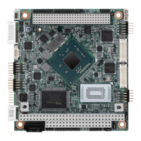
Connectors on the PCE-5126 single host board link it to external devices such as
hard disk drives and a keyboard. In addition, the board has a number of jumpers
used to configure your system for your application.
The tables below list the function of each of the board jumpers and connectors. Later
sections in this chapter give instructions on setting jumpers. Chapter 2 gives instruc-
tions for connecting external devices to your motherboard.
Table 1.1: Jumper list
Label Function
JCMOS1 CMOS clear
JMECLR1 ME setup clear
JWDT1 Watchdog Reset
JOBS1 HW Monitor Alarm
Table 1.2: Connector list
Label Function
LPT1 Parallel port, Parallel port x 1, supports SPP/EPP/ECP mode
LAN1 Intel 82579LM for all SKUs
LAN2 LAN 2: Intel 82583V for QG2 SKU; Intel 82574L for WG2 SKU
VGA1 VGA connector
KBMS1 PS/2 keyboard and mouse connector
KBMS2 External keyboard/mouse connector
COM1 Serial port: COM1; RS-232 (Box Header)
COM2 Serial port: COM2; RS-232 (Box Header)
JIR1 Infrared connector
JFP1 Power Switch / Reset connector
JFP2 External speaker / SATA HDD LED connector
JFP3
(Keyboard Lock and
Power LED)
Suspend: Fast flash (ATX/AT)
System On: ON (ATX/AT)
System Off: OFF (AT)
System Off: Slow flash (ATX)
JCASE1 Case Open
CPUFAN1 CPU FAN connector (4-pin)
LANLED1 LAN1/2 LED extension connector
HDAUD1 Connector for HD audio extension module
USB12 USB port 1, 2
USB34 USB port 3, 4
USB56 USB port 5, 6
USB78 USB port 7, 8
USB9 USB port 9
SATA1 Serial ATA1
SATA2 Serial ATA2
SATA3 Serial ATA3
SATA4 Serial ATA4
SATA5 Serial ATA5
SATA6 Serial ATA6