vii PCE-5126 User Manual
Contents
Chapter 1 Hardware Configuration......................1
1.1 Introduction ............................................................................................... 2
1.2 Features & Benefits................................................................................... 2
1.3 Specifications............................................................................................ 3
1.3.1 System.......................................................................................... 3
1.3.2 Memory......................................................................................... 3
1.3.3 Input/Output .................................................................................. 4
1.3.4 Graphics........................................................................................ 4
1.3.5 Ethernet LAN ................................................................................ 4
1.3.6 Industrial features ......................................................................... 4
1.3.7 Mechanical and environmental specifications............................... 4
1.4 Jumpers and Connectors.......................................................................... 5
Table 1.1: Jumper list .................................................................. 5
Table 1.2: Connector list.............................................................. 5
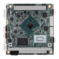
1.5 Board Layout: Jumper and Connector Locations...................................... 6
Figure 1.1 Jumper and connector locations................................. 6
1.6 PCE-5126 Block Diagram ......................................................................... 7
Figure 1.2 PCE-5126 block diagram............................................ 7
1.7 Safety Precautions.................................................................................... 8
1.8 Jumper Settings ........................................................................................ 8
1.8.1 How to set jumpers ....................................................................... 8
1.8.2 BIOS CMOS/ME data clear (JCMOS1/JMECLR1)....................... 9
Table 1.3: Clear BIOS CMOS/ME Data (JCMOS1/JMECLR1) ... 9
1.8.3 Watchdog timer output (JWDT1) ................................................ 10
Table 1.4: Watchdog timer output (JWDT1).............................. 10
Table 1.5: H/W monitor alarm (JOBS1).................................... 10
1.9 System Memory ...................................................................................... 10
1.10 Memory Installation Procedures.............................................................. 11
1.11 Cache Memory........................................................................................ 11
1.12 Processor Installation.............................................................................. 11
1.13 Processor Cooler Installation .................................................................. 13
Chapter 2 Connecting Peripherals ....................15
2.1 Introduction ............................................................................................. 16
2.2 Parallel Port (LPT1)................................................................................. 16
2.3 USB Ports (USB12, USB34, USB56, USB78) ........................................ 16
2.4 VGA Connectors (VGA1) ........................................................................ 17
2.5 Serial Ports (COM1 & COM2)................................................................. 17
2.6 PS/2 Keyboard and Mouse Connector (KBMS1/KBMS2)....................... 18
2.7 CPU Fan Connector (CPUFAN1)............................................................ 18
2.8 Front Panel Connectors (JFP1, JFP2 & JFP3) ....................................... 19
2.8.1 Power LED and keyboard lock (JFP3)........................................ 19
Table 2.1: PS/2 or ATX power supply LED status..................... 19
2.8.2 External speaker (JFP2) ............................................................. 20
2.8.3 Reset connector (JFP1).............................................................. 20
2.8.4 HDD LED connector (JFP2)........................................................ 20
2.8.5 ATX soft power switch (JFP1)..................................................... 20
2.9 H/W Monitor/Watchdog Timer/Infrared ................................................... 21
2.9.1 H/W Monitor Alarm (JOBS1)....................................................... 21
2.9.2 Watchdog Timer (JWDT1) .......................................................... 21
2.9.3 Infrared Interface (JIR1).............................................................. 21
2.10 LAN Ports (LAN1 & LAN2)...................................................................... 22
Table 2.2: LAN LED Indicators.................................................. 22