SAF_5523451_09
18
ELECTRIC CONNECTIONS
PRELIMINARY WARNINGS
Ensure supply voltage is correct (see identication plate applied
on the equipment); incorrect voltage would irreparably under-
mine the main equipment components.
Respect the connection indications of the phase, neutral and
earth wires.
Install a suitable protective power cut-o device with delayed
characteristic curve with contact openings of at least 3 mm and
with an adequate breaking capacity and dierential protection.
An ecient earth connection is mandatory; the manufacturer
cannot be responsible for damage caused by a lack of said con-
nection.
The power supply of the equipment must have a value between
± 10% of the value shown on the feature plate. If this is not re-
spected, you must contact your electrical service provider.
Use cables that comply with the standards in force in various
countries.
POWER SUPPLY CONNECTION
The equipment is supplied with a plug to be inserted into a
socket.
If necessary you can extend the cable.
In this case:
Use an approved extension cord that is adequate to the equip-
ment absorption.
AUXILIARY CONNECTIONS
For the auxiliary connections you must access the terminal board.
Remove the top cover (see chapter 2.7Access to inner parts p.
17)
Unscrew the locking screws.
Open the electrical panel door.
Insert the connection cables into the same hole used for the
power cable.
Next:
Insert the cables into the cable guides on the electrical panel.
Connect to the terminal board.
Refer to the supplied wiring diagrams for connections to the
heat pump
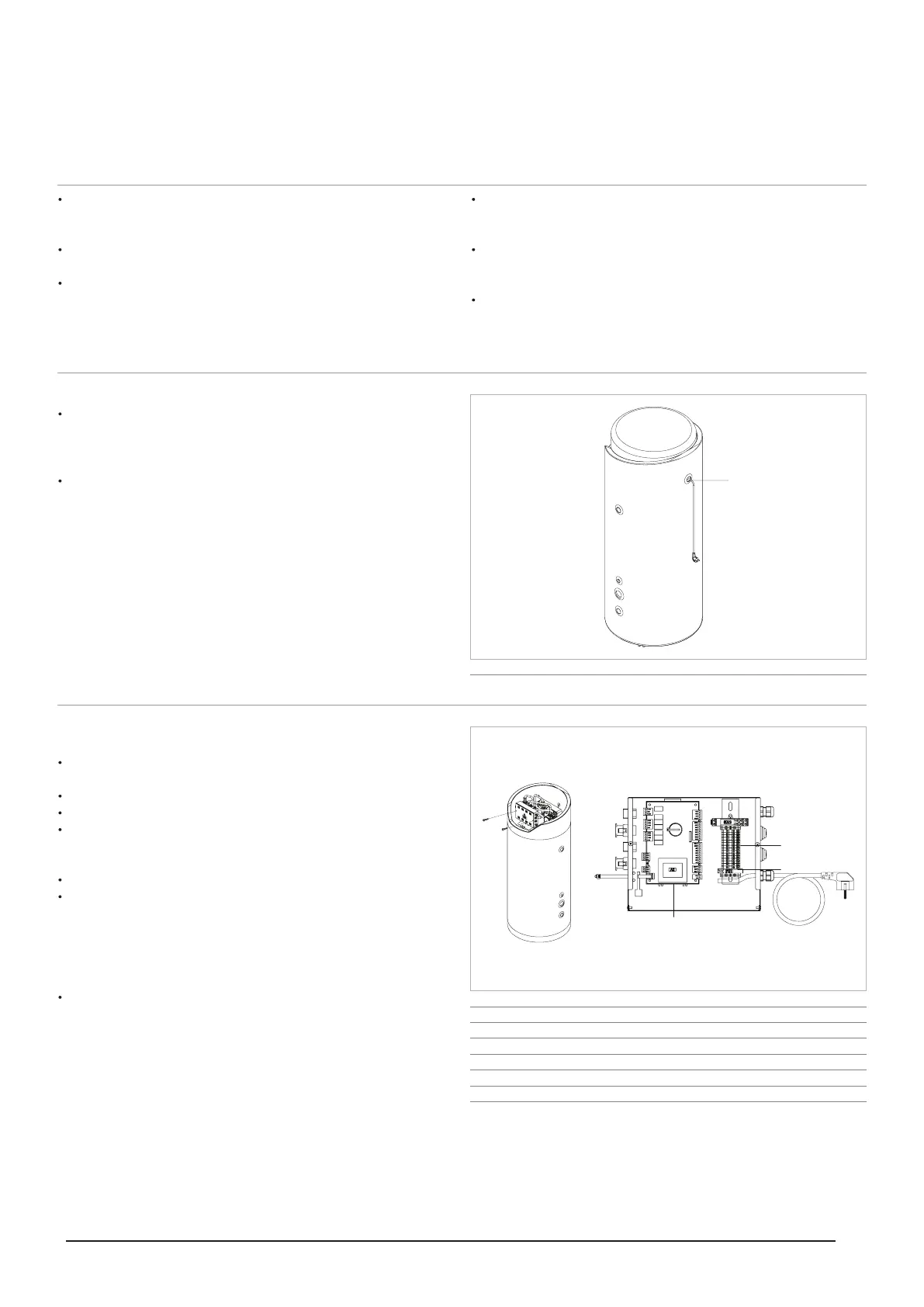
1. Power cable
1
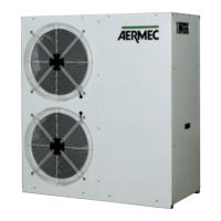
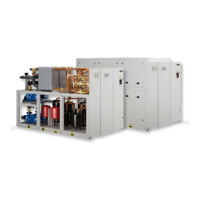
1. Control panel connection cable
2. Electronic controller
3. Power cable
4. 230 V, 5x20 T, 3.15 A Auxiliary fuse
5. Auxiliary connection input
6. Auxiliary connection terminal board
7. Resistance kit connection cable input
Cable length = 1.5 m
2
5
6
3
4
7
1