Hardware Reference Guide 109
Appendix A Wiring Diagrams and
Antenna Orientation
This appendix contains descriptions of pin assignments, cabling diagrams, and antenna configuration
information for Aerohive devices, in the following sections:
• "Power over Ethernet Port Pin Assignments" on page 110
• "Smart PoE" on page 111
• "Aggregate Interface" on page 112
• "Redundant Interface" on page 113
• "RJ45 Console Port Pin Assignments" on page 113
• "Aggregate and Redundant Interfaces" on page 112
• "DB9 Console Port Pin Assignments" on page 114
• "Configuring Antennas" on page 115
• "Single-direction Antennas" on page 115"Omnidirectional Antennas" on page 116
• "MIMO" on page 116
• "Using MIMO with Legacy Clients" on page 118
ETHERNET PORT PIN ASSIGNMENTS
The following sections contain pin assignments and wiring information for standard and PoE (power over
Ethernet) Ethernet ports for Aerohive devices.
Standard (non-PoE) Ethernet Port Pin Assignments
Standard (non-PoE) Ethernet ports in Aerohive devices follow the TIA/EIA-568-B standard. Figure 1 shows the
pin assignments and port LEDs for a non-PoE Ethernet port.
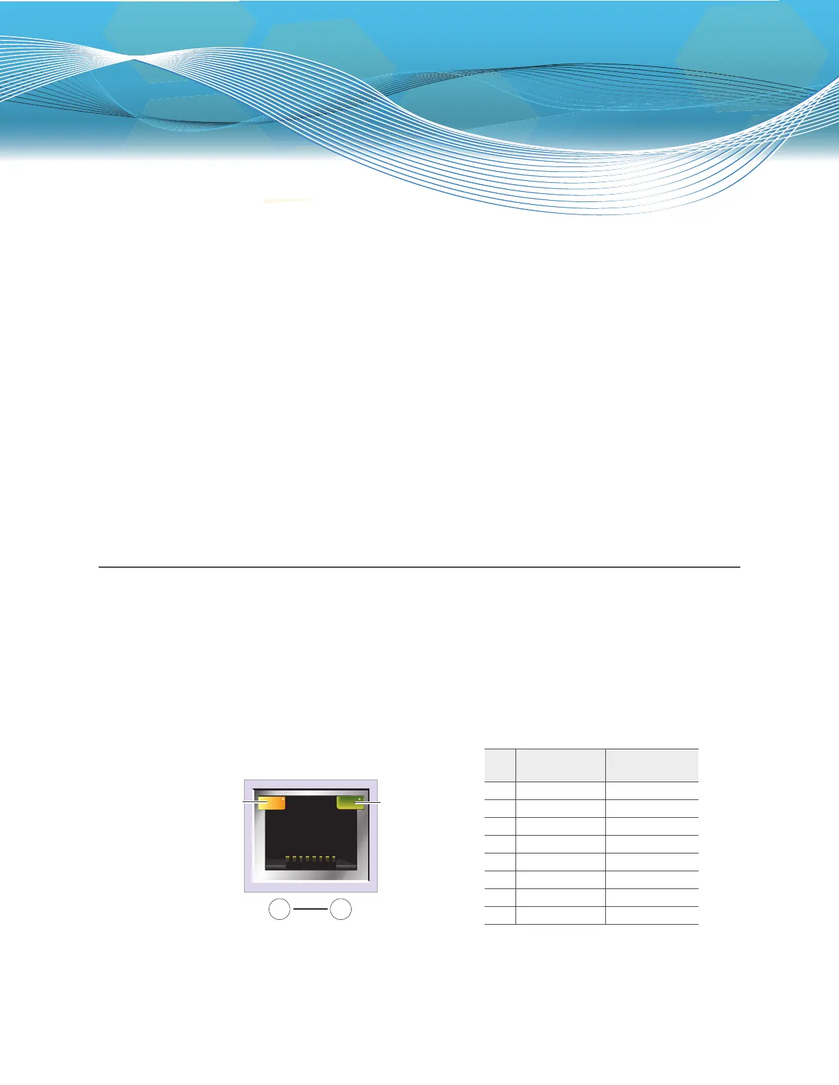
Figure 1 Non-PoE Ethernet port LEDs and pin assignments
Link rate LED
Dark: No link
Green: 100 Mbps
Amber: 1 Gbps
(An Ethernet port on the
HiveManager Appliance)
Link activity LED
Dark: Link is down
Steady amber: Link is
up but inactive.
Blinking amber: Link is
up and active
8 1
Pin numbers
Pin
10/100Base-T
Data Signal
1000Base-T
Data Signal
1Transmit + BI_DA+
2Transmit - BI_DA-
3 Receive + BI_DB+
4 (unused) BI_DC+
5 (unused) BI_DC-
6 Receive - BI_DB-
7 (unused) BI_DD+
8 (unused) BI_DD-
Legend: BI_D = bidirectional
A+/A- B+/B- C+/C- D+/D- = wire pairings