Chapter 4 The AP320 Platform
44 Aerohive
Reset Button
To reset the device, or restore the factory configuration, insert a paper clip, or similar tool, into the Reset
pinhole and press the reset button. To reboot the device, hold the button down between 1 and 5 seconds.
To return the configuration to the factory default settings, hold it down for at least 5 seconds. After releasing
the button, the Power LED goes dark as the system reboots. Then it pulses green while the firmware loads
and the system performs a self-test. After the software finishes loading, the Power LED glows steady green.
To disable the reset button from resetting the configuration, enter this command: no reset-button
reset-config-enable Pressing the button between 1 and 5 seconds will still reboot the AP320, but
pressing it for more than 5 seconds will not reset its configuration.
Status LEDs
The five status LEDs on the top of the AP320 indicate various states of activity through their color (dark,
green, amber, and red) and illumination patterns (steady glow or pulsing). The meanings of the various color
and illumination patterns for each LED are explained below.
Power
• Dark: No power
•
Green (steady): Powered on and the firmware is running normally
•
Green (flashing): Firmware is booting up
•
Amber (steady): Firmware is being updated
•
Amber (flashing): Alarm indicating a firmware issue has occurred
•
Red (steady): Alarm indicating a hardware issue has occurred
ETH0 and ETH1
• Dark: Ethernet link is down or disabled
•
Green (steady): 1000 Mbps Ethernet link is up but inactive
•
Green (flashing): 1000 Mbps Ethernet link is up and active
•
Amber (steady): 10/100 Mbps Ethernet link is up but inactive
•
Amber (flashing): 10/100 Mbps Ethernet link is up and active
WIFI0 and WIFI1
• Dark: Wireless interface is disabled
•
Green (steady): Wireless interface is in access mode but inactive
•
Green (flashing): Wireless interface is in access mode and active
•
Amber (steady): Wireless interface is in backhaul mode but inactive
•
Amber (flashing): Wireless interface is in backhaul mode and is connected with other hive members
•
Green and amber (alternating): Wireless interface is in backhaul mode and is searching for other
hive members
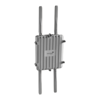
Antennas
Antennas are an integral part of the AP320. The AP320 has six internal single-band antennas. Three of the
antennas operate in the 2.4-GHz band (IEEE 802.11b/g/n) and have a 2-dBi gain. The other three antennas
operate in the 5-GHz band (IEEE 802.11a/n) and have a 3-dBi gain. All antennas are omnidirectional,
providing fairly equal coverage in all directions in a cardioid (heart-shaped) pattern around each antenna
(see Figure 7 on page 116).
The three 2.4-GHz antennas link to radio 1, and the three 5-GHz antennas link to radio 2. Conceptually, the
relationship of antennas and radios is shown in Figure 2 on page 45.