Chapter 2 AP121 and AP141 Platforms
18 Aerohive
AP121 AND AP141 PRODUCT OVERVIEW
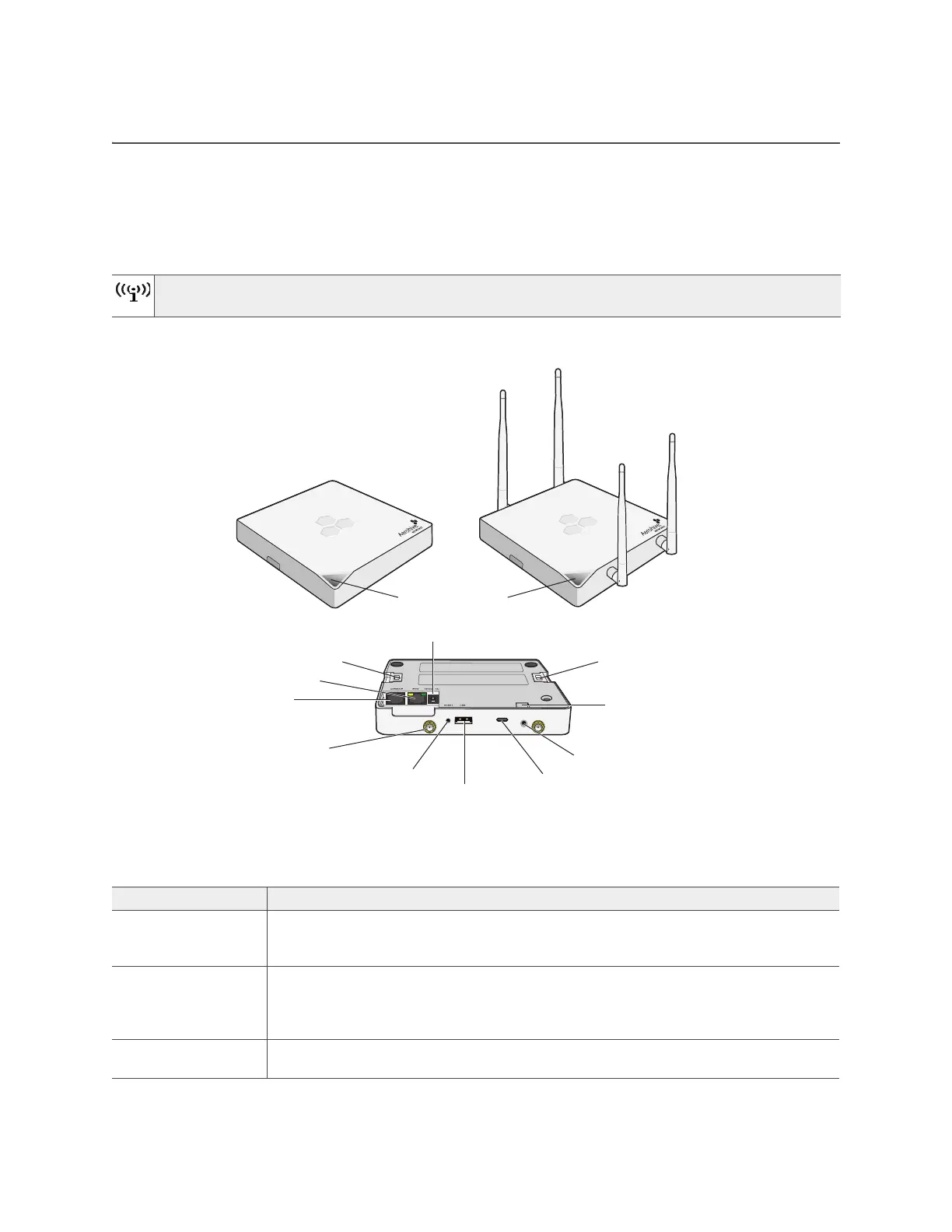
The AP121 and AP141 models provide excellent throughput and coverage. The AP121has two internal
antennas, and the AP141 has four detachable external antennas. You can see these hardware
components in Figure 1. Each component is described in Table 1 "AP121 and AP141 component
descriptions".
Figure 1 AP121 and AP141 hardware components
To meet federal radiation exposure requirements, these devices should be installed at a minimum
distance of 23 cm or 9.06" from your body.
Table 1 AP121 and AP141 component descriptions
Component Description
Status indicator The status indicator conveys operational states for system power, firmware updates,
Ethernet and wireless interface activity, and major alarms. See "Status Indicator" on
page 20.
2.4 and 5 GHz
RP-SMA connectors
(AP141)
You can connect up to four detachable single-band antennas (two 2.4 GHz and
two 5 GHz) to the male 802.11a/b/g/n RP-SMA (reverse polarity-subminiature
version A) connectors. The antennas and the connectors are labeled for easy
identification. See "Antennas" on page 21.
Console port You can access the CLI by making a serial connection to the RJ45 console port. See
"Console Port" on page 20.
Console port
ETH0 LAN port
AP121 and AP141 components (chassis shown upside down)
AP141
Reset
External antenna
connectors
(AP141 only, two 2.4
GHz and two 5 GHz)
USB modem port
Device lock slot
Security tab cavity
Mounting tab
Power connector
Security screw hole
Mounting tab
AP121
Status indicator