Chapter 7 The SR2024 Switch
74 Aerohive
PRODUCT OVERVIEW
The Aerohive SR2024 Switch provides advanced network edge features including cloud-enabled
management, on-demand provisioning, and secure branch routing. The SR2024 offers Gigabit Ethernet
switching and advanced features that include user-based QoS, storm control, 802.1x multiple
authentication for voice and data, as well as traditional switching features such as LLDP, Spanning Tree,
3G/4G connectivity, and IGMP snooping. The SR2024 has 24 Ethernet ports (eight of which provide PoE
power), four SFP uplink ports, an RJ45 Console port, and a USB port for WAN connection redundancy.
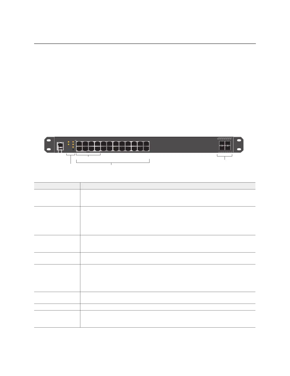
Figure 1 shows the SR2024 hardware components. Each component is described in Table 1 "SR2024
hardware component descriptions".
Figure 1 The SR2024 switch hardware components
Table 1 SR2024 hardware component descriptions
Component Description
Console port You can access the command line interface (CLI) for management and
troubleshooting by making a serial connection to the RJ45 console port. See
"Console Port" on page 77.
USB modem port The Type-A USB 2.0 port (backward compatible with USB1.1) located below the
Console port allows you to connect a wireless 3G/4G USB modem to serve as a
WAN connection.
For specific information about the modems supported for the SR series switches and
configuration settings, refer to HiveManager Help.
Power LED The Power LED is located on the left side of the front panel. This LED indicates when
the device is powered on. See "Changing the Temperature and Fan Speed Alarm
Thresholds" on page 79.
Reset button The reset button allows you to reboot the device or reinstate the default factory
settings. See "Reset Button" on page 77.
LEDs mode button The LEDs mode button allows you to cycle through the port LED modes, (Link,
Duplex, Speed, and PoE). To select a mode, press the LEDs button until the desired
mode LED lights. The port LEDs then indicate the port status for that mode.
See"Changing the Temperature and Fan Speed Alarm Thresholds" on page 79 and
Figure 3 on page 80.
Link LED mode When you select Link LED mode, the port LEDs indicates the link activity on the port.
See "Changing the Temperature and Fan Speed Alarm Thresholds" on page 79.
Stack LED mode The Stack LED is reserved for future use.
Duplex LED mode When you select Duplex mode, the port LEDs indicate whether the port is operating
in duplex mode. See "Changing the Temperature and Fan Speed Alarm Thresholds"
on page 79.
25 26
27 28
1 2
O O
3 4
O O
5 6
O O
7 8
O O
9 10
O O
11 12
O O
13 14
O O O O
15 16
O O
17 18
O O
19 20
O O
21 22
O O
23 24
Console
Link
Speed
Duplex
PoE
LEDs
Power
Stack
Reset
SR2024 front panel
Console port
LEDs and
Reset button
Ethernet ports
SFP uplink ports
SR
202
PoE
PoE ports
USB port
Power connector (rear panel)
Fans
(side panel)