Hardware Reference Guide 45
MOUNTING THE AP320
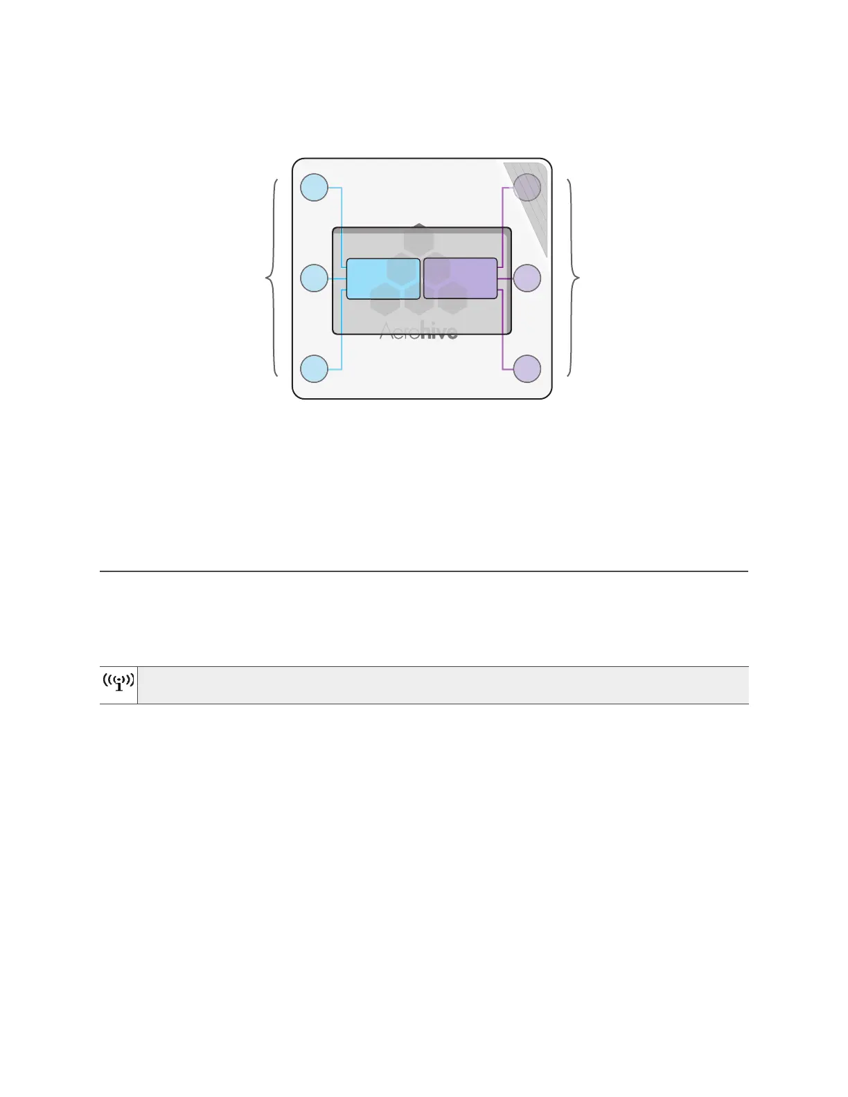
Figure 2 Antennas and radios
The wifi0 interface links to radio 1 (frequency range = 2.4
GHz for IEEE 802.11b/g), and the wifi1 interface links
to radio 2 (frequency range = 5 GHz for IEEE 802.11a). These interface-to-radio relationships are permanent.
Although hive members automatically adjust their signal strength according to their environments, you can
resize the area of coverage by increasing or decreasing the signal strength manually by entering the
interface { wifi0 | wifi1 } radio power <number> command, where <number> can be from 1 to
20 and represents a value in dBm.
MOUNTING THE AP320
Using the mounting plate and track clips, you can mount the AP320 to the tracks of a dropped ceiling grid.
Using just the mounting plate, you can mount the AP320 to any surface that supports its weight (2 lb., 0.9 kg).
Ceiling Mount
To mount the AP320 to a track in a dropped ceiling, you need the mounting plate, two track clips, and two
Keps nuts, all of which ship as an option with the AP320. You also need a screwdriver and—most likely—a
ladder.
Nudge the ceiling tiles slightly away from the track to clear some space. Fasten the track clips to the
mounting plate, and then attach them to the ceiling track, as shown in Figure 3 on page 46.
You can also mount the AP320 on a table using the four rubber feet that ship with the product. Peel
the rubber feet off the adhesive sheet and press them on each underside corner of the device.
2.4 GHz
Antennas
5 GHz
Antennas
Radio 1
RF 802.11b/g/n
2.4 GHz
Radio 2
RF 802.11a/n
5 GHz
Cut-away view of the AP to show the relationship of the
antennas and the two internal radios