Chapter 4 The AP320 Platform
48 Aerohive
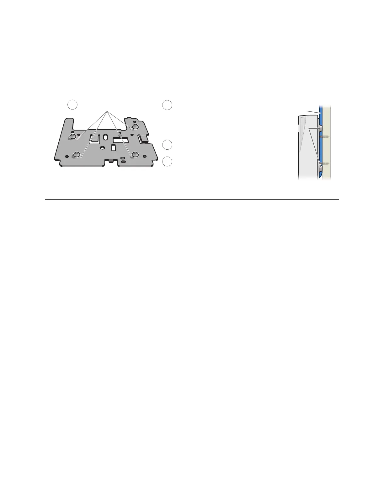
If you do not pass the cables through a hole, you can run them along the wall between the wall and the
mounting plate. To create space for the cables, attach the rubber feet to the mounting plate before
attaching it to the wall. The recommended positions for the four rubber feet and the mounting instructions
are shown in Figure 7.
Figure 7 Using the rubber feet to provide clearance for cables
DEVICE, POWER, AND ENVIRONMENTAL SPECIFICATIONS
Understanding the range of specifications for the AP320 is necessary for optimal deployment and device
operation. The following specifications describe the physical features and hardware components, the
power adapter and PoE (Power over Ethernet) electrical requirements, and the temperature and humidity
ranges in which the device can operate.
Device Specifications
• Chassis dimensions: 8" W x 1.5" H x 8" D (20 cm W x 3.8 cm H x 20 cm D)
• Weight: 2 lb. (0.9 kg)
• Antennas: Three omnidirectional 802.11b/g/n antennas, and three omnidirectional 802.11a/n antennas
• Serial port: RJ45 (bits per second: 9600, data bits: 8, parity: none, stop bits: 1, flow control: none)
• Ethernet ports: two autosensing 10/100/1000 Base-T/TX Mbps ports; the ETH0 port is compliant with the
IEEE 802.3af and 802.at standards for PoE (Power over Ethernet)
Power Specifications
• AC/DC power adapter:
• Input:100 – 240 VAC
• Output: 48V/0.38A
• PoE nominal input voltages:
• 802.3af: 48 V/0.35A
• 802.3at: 48 V/0.625A
• RJ45 power input pins: Wires 4, 5, 7, 8 or 1, 2, 3, 6
Environmental Specifications
• Operating temperature: 32 to 104 degrees F (0 to 40 degrees C)
• Storage temperature: -4 to 158 degrees F (-20 to 70 degrees C)
• Relative Humidity: Maximum 95% (noncondensing)
Mounting plate
Attach the four rubber feet.
Run all the cables between the
mounting plate and the wall before
fastening the plate in place with the
screws. The rubber feet provide
clearance for the cables to pass.
Connect the cables to the ETH0 and
ETH1 ports and power connector.
Attach the AP to the mounting plate.
AP
Cables
1
2
3
4
(Side view)
Rubber feet
Side of wall