Hardware Reference Guide 111
ETHERNET PORT PIN ASSIGNMENTS
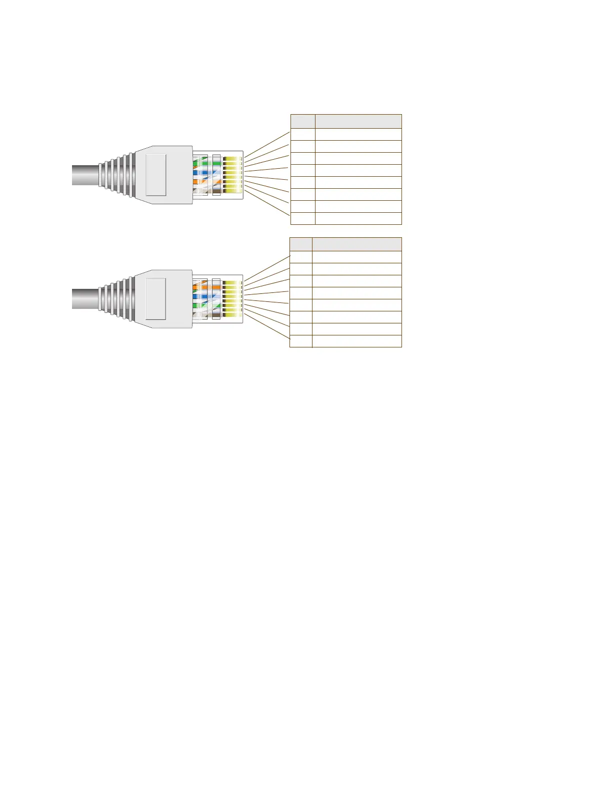
Figure 3 T568A and T568B wiring diagram
T568A and T568B are two standard wiring termination schemes. The only difference between them is that the
white/green + solid green pair of wires and the white/orange + solid orange pair of wires are reversed.
For straight-through Ethernet cables—using either the T568A or T568B standard—the eight wires terminate at
the same pins on each end.
For crossover Ethernet cables, the wires terminate at one end according to the T568A standard and at the
other according to T568B.
Smart PoE
The AP320, AP340, BR200-WP, and SR2024 switch apply the Aerohive concept of smart PoE (power over
Ethernet) to adjust power consumption as necessitated by varying levels of available power. The AP340 and
BR200-WP support PoE on the ETH0 or ETH1 interfaces and can draw power through either one or through
both simultaneously. The SR2024 switch supports power on Ethernet ports 1 through 8. Based on the available
power that the device detects, it manages internal power use by making the following adjustments:
• No adjustments are needed when the power level is 20 W (watts) or higher. If the available power drops
to a range between 18 and 20 W, the device disables its ETH1 interface, assuming that it is drawing
power through its ETH0 interface. If it is drawing power solely through its ETH1 interface, then it disables its
ETH0 interface instead.
• If the power level drops to the 15 – 18 W range, the device then switches from 3x3 MIMO (Multiple In,
Multiple Out) to 2x3 (see "MIMO" on page 116).
• In rare cases when the power drops between 13.6 and 15 W and further power conservation is
necessary, the device reduces the speed on its active Ethernet interface—ETH0 or ETH1—from
10/100/1000 Mbps to 10/100 Mbps.
• Finally, in the event that there is a problem with the PoE switch or Ethernet cable and the power falls
between 0 and 13.6 W, the device disables its wireless interfaces and returns its ETH0 and ETH1 interfaces
to 10/100/1000 Mbps speeds.
Through the application of smart PoE, the device can make power usage adjustments so that it can
continue functioning even when the available power level drops.
Pin T568A Wire Color
1 White/Green
2Green
3 White/Orange
4Blue
5 White/Blue
6Orange
7 White/Brown
8Brown
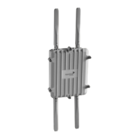
Pin T568B Wire Color
1 White/Orange
2 Orange
3 White/Green
4Blue
5 White/Blue
6 Green
7 White/Brown
8Brown
T568A-terminated Ethernet
cable with an RJ45 connector
T568B-terminated Ethernet
cable with an RJ45 connector