Replacing Assemblies 6
16901A Logic Analysis System Service Guide 57
To remove and replace the front panel assembly
1 Perform previous procedures:
• “To prepare the instrument for disassembly” on
page 46.
• “To remove and replace the cover” on page 50.
2 Disconnect the following cables:
• USB cables from the motherboard.
• Display cable from the display board (use care when
disconnecting to avoid damage).
• Touch screen cable from the touch screen controller
board.
• Keyboard cable from the keypad board.
• Front panel cable from the backlight inverter board.
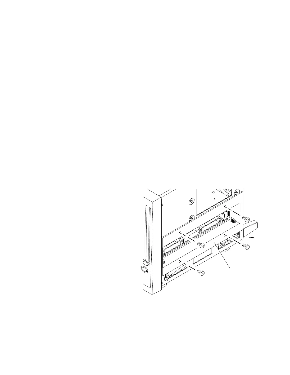
3 Using a Torx T10 screwdriver, remove 4 screws that
secure the shroud to the chassis.
4 Remove the shroud.

 Loading...


