64 16901A Logic Analysis System Service Guide
6 Replacing Assemblies
To remove and replace the display assembly
1 Perform previous procedures:
• “To prepare the instrument for disassembly” on
page 46.
• “To remove and replace the cover” on page 50.
• “To remove and replace the front panel assembly” on
page 57.
• “To remove and replace the backlight inverter board”
on page 59.
• “To remove and replace the front panel bracket
assembly” on page 62.
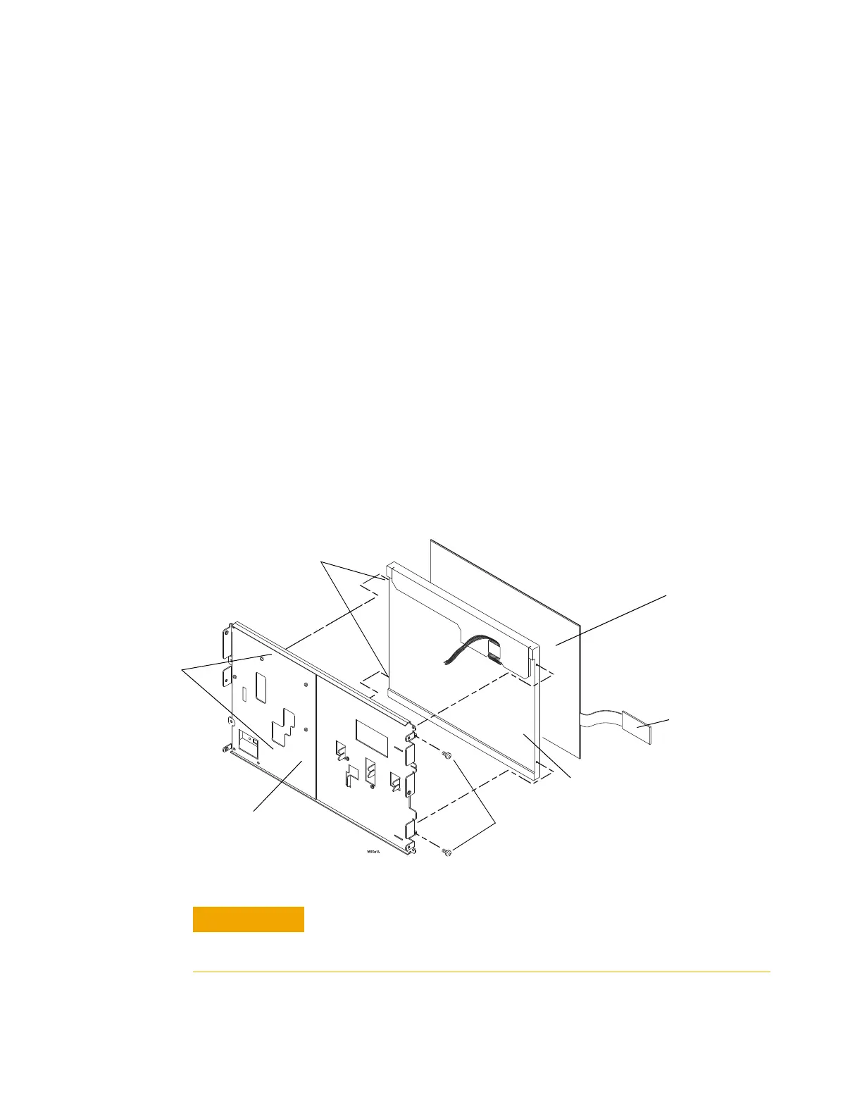
2 Using a Torx T10 screwdriver, remove the 2 screws
securing the display assembly to the front panel bracket
assembly.
3 Remove the alignment pins on the bracket from the holes
on LCD.
Handle the touch screen and LCD display by the edges only. If
necessary, clean with alcohol and a lint-free wipe or remove any
airborne contamination with ionized air.
T-10 screws (2)
Front panel
assembly
bracket
Liquid crystal
display (LCD)
Touch screen
control board
assembly
Alignment
pins
Alignment
holes
Tou c h s c r e e n
 Loading...


