Replacing Assemblies 6
16901A Logic Analysis System Service Guide 71
92 mm fans
1 Perform previous procedures:
• “To prepare the instrument for disassembly” on
page 46.
• “To remove and replace the cover” on page 50.
• “To remove and replace the front panel assembly” on
page 57.
• “To remove and replace the tray assembly” on page 69.
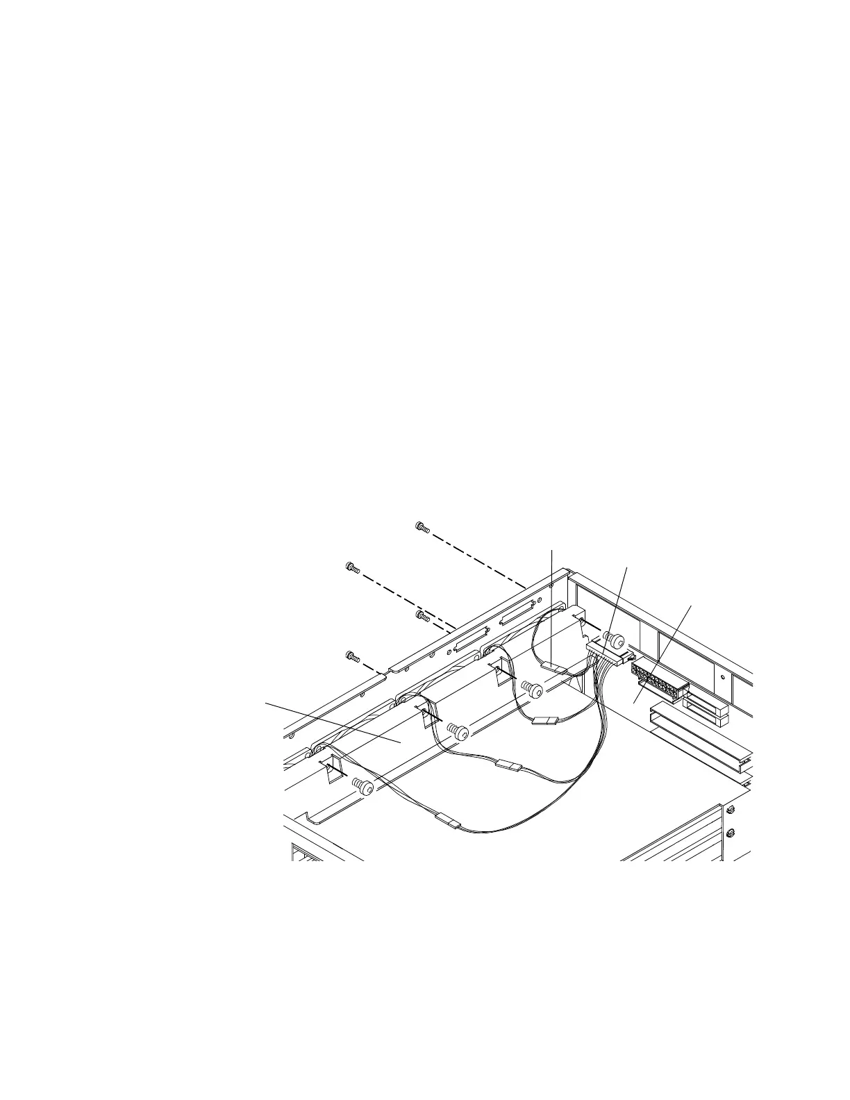
2 Using a Torx T10 screwdriver, remove the 4 screws
securing the baffle to the chassis.
3 Disconnect the fan cable for the fan you are replacing
from the fan cable assembly. If replacing all fans,
disconnect the fan cable assembly from the module
interface board.
4 Using a Torx T25 screwdriver, remove the 4 screws
securing the fan to the rear of the chassis.
5 Reverse this procedure to replace the fan(s).
T-25
screws
(4)
Fan cable
assembly
Module
interface board
Fan cable
Baffle
 Loading...


