102
Chapter 4 Calibration and Adjustment
-24 dB Range Flatness Verification
4
3 Set the instrument to each output described in the table below and
measure the output amplitude with the AC Voltmeter. This will become
the reference measurement. Set the output impedance to 50 . Be sure
the output is enabled.
4 Set the measured value in Step 3 to be the reference value on the AC
Voltmeter.
5 Set the instrument to each output described in the table below and
measure the output amplitude relative to the source as a percent with
the AC Voltmeter. Note that the table also lists the output in dB if you
are using a power meter to perform this test.
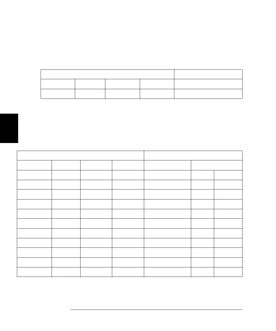
Waveform Generator Measurement
Output Setup Function Amplitude Frequency Nominal Error
Q 50 Sine Wave 0.190 Vrms 1.000 kHz 0.190 Vrms ± 0.0026 Vrms
Waveform Generator Measurement
Output Setup Function Amplitude Frequency Nominal Error Nominal Error
50 Sine Wave 0.190 Vrms 100.000 kHz 100% ±1.15% 0 dB ±0.10 dB
50 Sine Wave 0.190 Vrms 500.000 kHz 100% ±1.74% 0 dB ±0.15 dB
50 Sine Wave 0.190 Vrms 1.000 MHz 100% ±1.74% 0 dB ±0.15 dB
Q 50 Sine Wave 0.190 Vrms 2.000 MHz 100% ± 1.74% 0 dB ±0.15 dB
50 Sine Wave 0.190 Vrms 5.000 MHz 100% ±1.74% 0 dB ±0.15 dB
50 Sine Wave 0.190 Vrms 10.00 MHz 100% ±3.51% 0 dB ±0.30 dB
50 Sine Wave 0.190 Vrms 15.00 MHz 100% ±3.51% 0 dB ±0.30 dB
50 Sine Wave 0.190 Vrms 20.00 MHz 100% ± 3.51% 0 dB ±0.30 dB
50 Sine Wave 0.190 Vrms 22.00 MHz 100% ± 4.71% 0 dB ±0.40 dB
50 Sine Wave 0.190 Vrms 27.00 MHz 100% ±4.71% 0 dB ±0.40 dB
50 Sine Wave 0.190 Vrms 30.00 MHz 100% ± 4.71% 0 dB ±0.40 dB
 Loading...