113
Chapter 4 Calibration and Adjustment
Output Impedance Adjustment
4
4
Output Impedance Adjustment
The waveform generator stores calibration constants for the output
Impedance of the instrument. The output impedance constants are
generated with and without the post-amplifier attenuator.
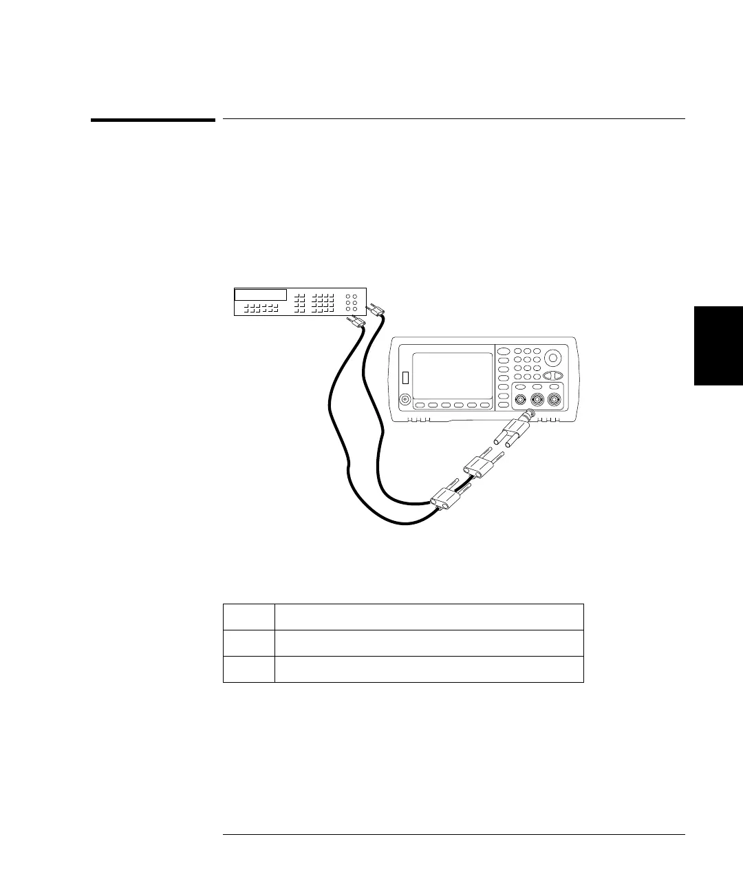
1 Set the DMM to measure offset-compensated, four-wire Ohms. Set the
DMM to use 100 NPLC integration. Connect the Ohms Source and Ohms
Sense DMM inputs to the Channel 1 output as shown below.
2 Use the DMM to make a 4-wire resistance measurement at the front
panel Output connector for each setup in the following table. The
expected measured value is approximately 50 .
* Constants are stored after completing this setup.
3 Using the numeric keypad or knob, adjust the displayed impedance at
each setup to match the measured impedance. Select ENTER VALUE.
4 There are no specific operational verification tests for Output
Impedance. Continue with the next adjustment procedure in this
chapter.
Setup
8* -24 dB post-attenuator range
9* 0 dB range
 Loading...