Input Amplifier
Unless otherwise noted, components in this discussion are located on
the A4 circuit assembly (34970-66504). The schematics are included
in Chapter 8 starting on page 234.
The DC Amplifier circuit is used by every measuring function except
frequency and period. Analog switch U101B selects various input
signals for measurement by the ADC. Switch U101B has three
sources which can be dynamically selected: measure customer input
(MC), measure zero input (MZ), and precharge (PRE). The MC state is
the actual input measurement. The MZ state measures internal
offset voltages which are also present in the MC measurement. The
final measurement result is computed from MC–MZ. The PRE state
is used to “precharge” internal capacitances to reduce charge
injection to the input terminal from the dynamic switching of MC and
MZ. Autozero off disables the dynamic switching of the amplifier
input. However, a new MZ value is automatically taken whenever a
new function or range is selected, even if autozero is turned off.
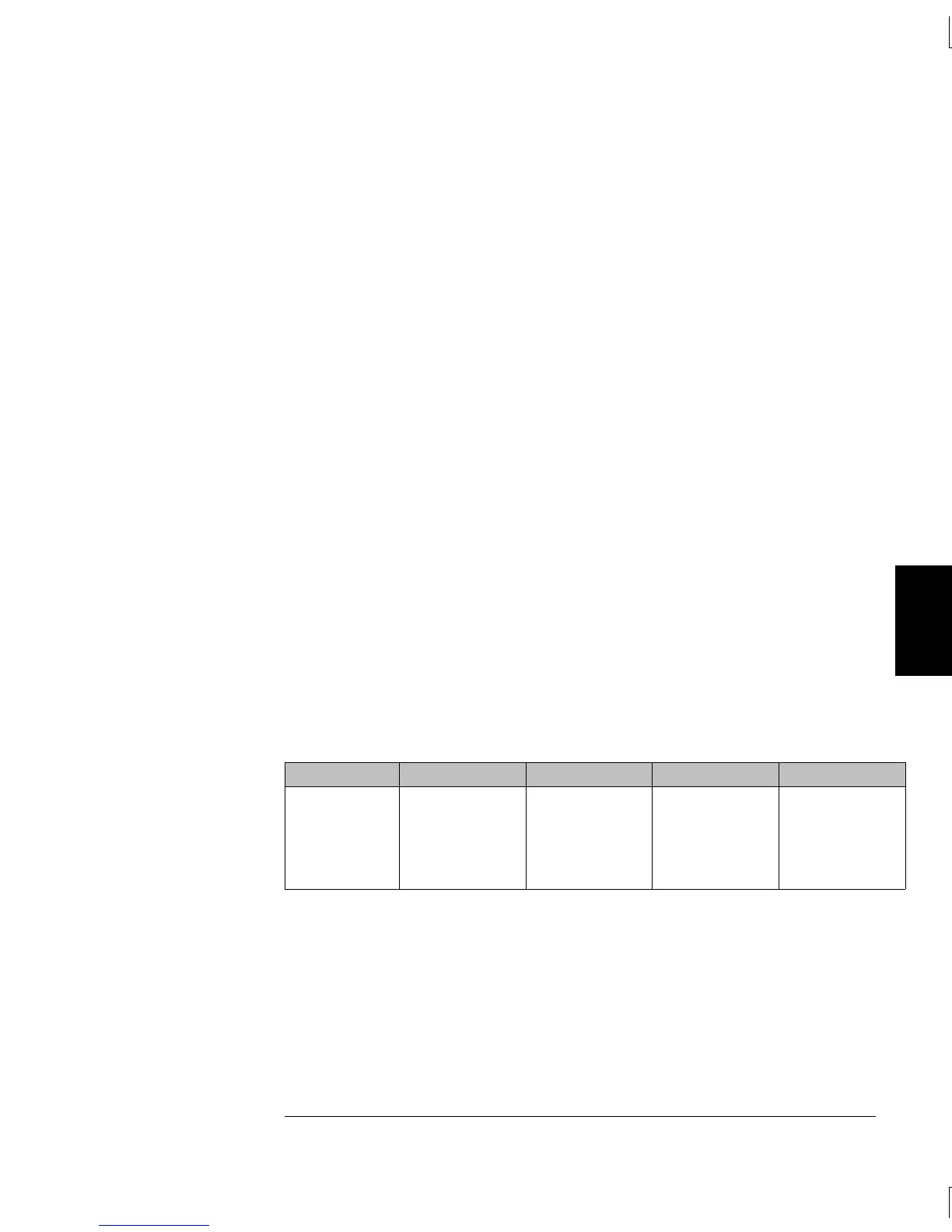
In the dc voltage function, ranging is accomplished through both
input relay switching (K102–K104) and solid state switching (U101).
As a result, the input to the
ADC has the same nominal 10 V value for
a full scale input on each range. The dc input amplifier is comprised
of source follower dual FET U104, amplifier U106, and associated
bias circuitry. The feedback resistors U102C and switches U101C
select non-inverting amplifier gains of x1, x10, and x100 for the dc
input amplifier circuit. Amplifier output ADIN drives the dc input to
the a-to-d converter for all measuring functions.
DCV Range U102A Divider U101 Input Amplifier Gain ADC Input
100 mV
1 V
10 V
100 V
1000 V
1/100
1/100
Pin 5
Pin 5
Pin 5
Pin 8
Pin 8
x100
x10
x1
x10
x1
10 V
10 V
10 V
10 V
10 V
5
Chapter 5 Theory of Operation
Internal DMM
131

 Loading...

