34905A/34906A
Components in this discussion are located on the A1 circuit assembly
(34905-66501 or 34906-66501). The schematics are included in
Chapter 8 starting on page 258.
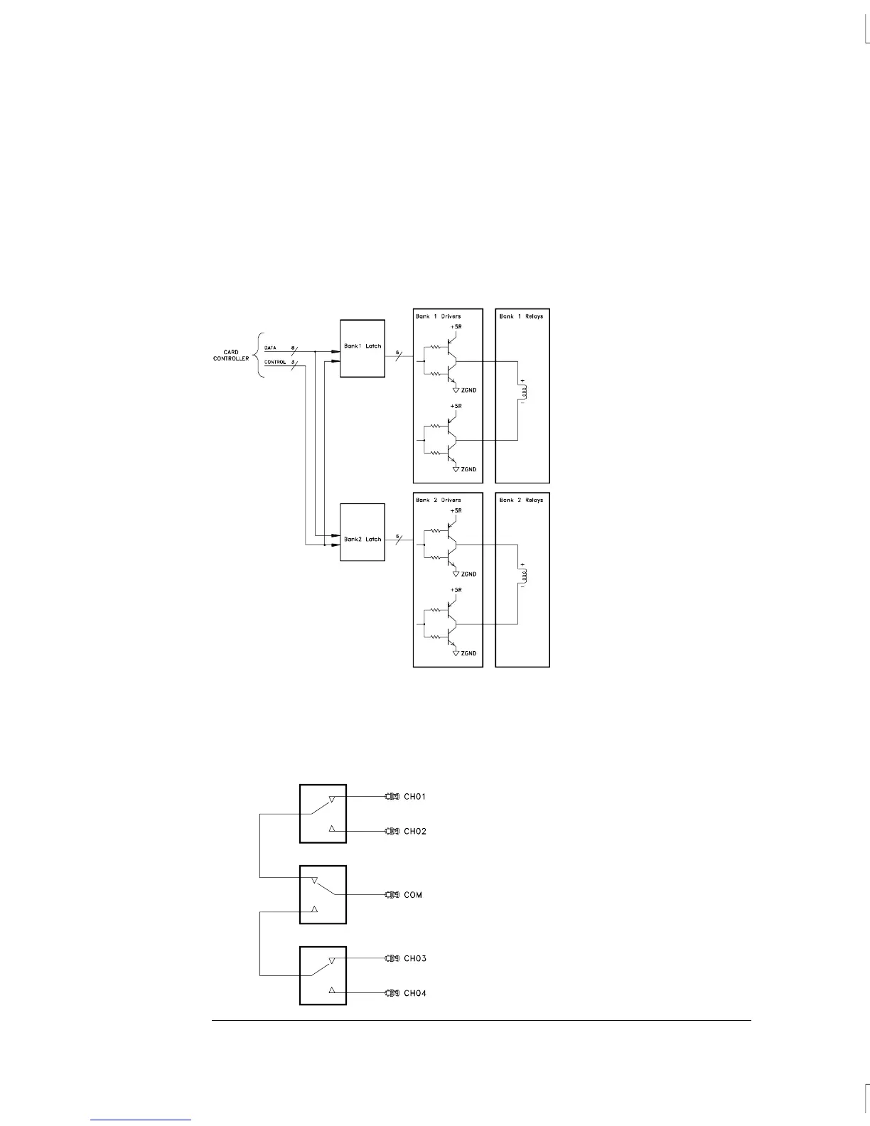
The control circuitry has of two grouping of buffers, relay drivers and
relays, one for each multiplexer bank.
Bank1 latch, U102, and Bank2 latch, U103, control the relays. The bank
drivers are divided into six groups of set and reset drivers. Each set
and reset driver controls one relay. The column drivers operate as a
pair. There are six column drivers each controlling a relay. The relays
are arranged into two independent banks:
Chapter 5 Theory of Operation
Switch Modules
148

 Loading...

