34904A
Components in this discussion are located on the A1 circuit assembly
(34904-66501). The schematics are included in Chapter 8 starting on
page 254.
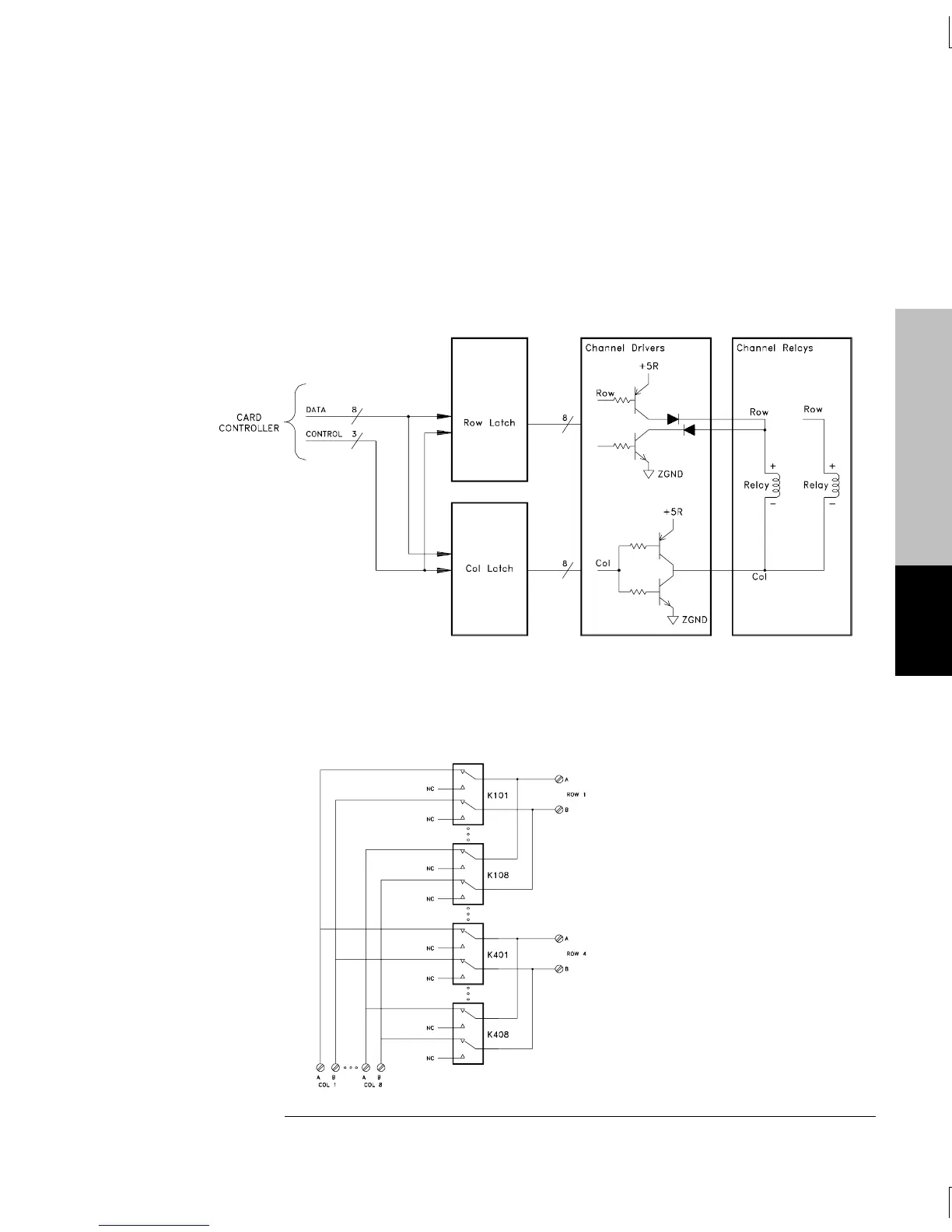
The control circuitry has four groupings of latches, relay drivers and
relays divided into 4 rows by 8 columns.
The row latch, U102, and column latch U103, control the relays.
The row drivers are divided into four groups of set and reset drivers.
Each group of row drivers controls eight relays. The column drivers
operate as a pair. There are eight column drivers each controlling
four relays. The relays are arranged in 4 rows by 8 columns.
Module Reference
5
Chapter 5 Theory of Operation
Switch Modules
147

 Loading...

