U101 controls the relays on the module using an 8-bit data bus and
three control lines. The data lines are latched and applied to the
relay drivers.
U101 enters a low-power idle mode when inactive. U101 responds
when a command is received or when a scheduled reference junction
temperature measurement is taken.
The relays use a buffered +5 Volt power supply. U101 supplies two
drive enable lines (DR_EN and +5NL_EN) that connect Vcc from the
digital bus with the relay drive lines through Q101 (+5R or +5NL).
To minimize the current through DGND caused by static discharge,
the ground return (ZGND) is isolated from the backplane ground
through a bead L102.
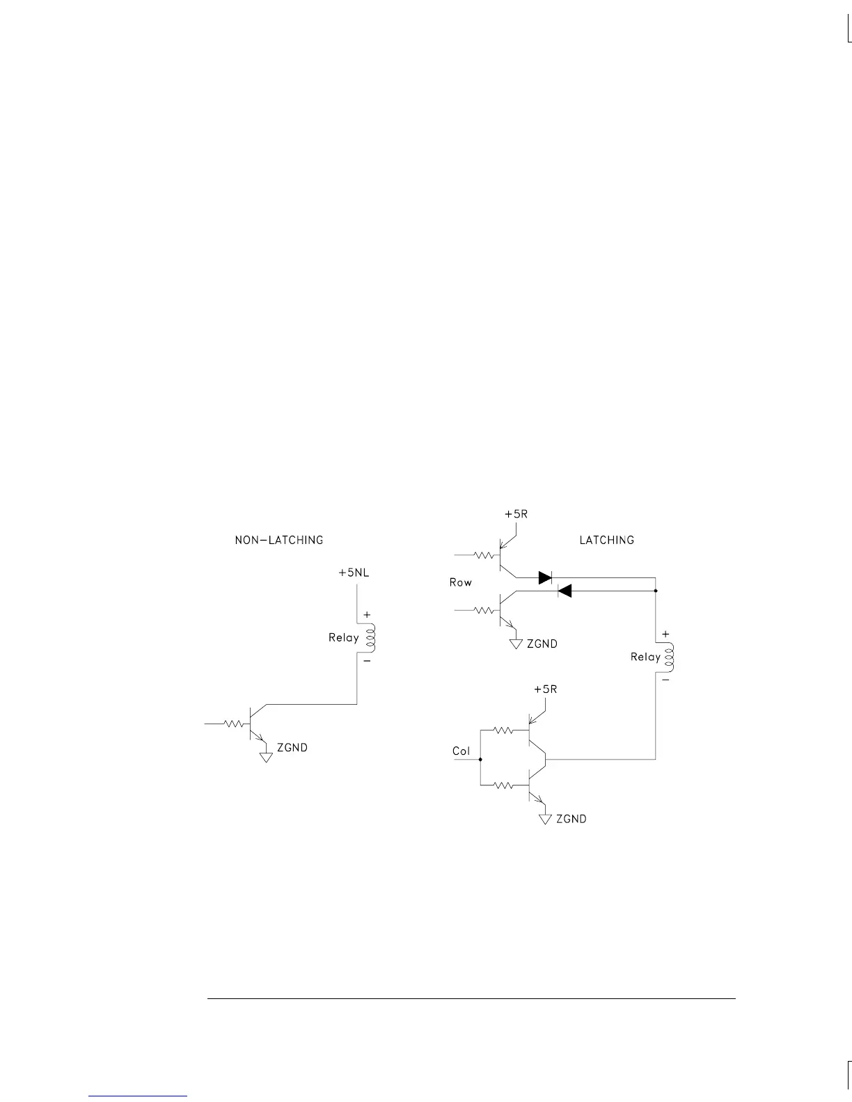
Relay Drivers
Two types of single-coil relays are used on the switch modules:
latching and non-latching. Typical driver configurations are shown below.
Chapter 5 Theory of Operation
Switch Modules
140
 Loading...


