Home
Agilent Technologies
Switch
34970A
Service Guide
Page 46 (To Adjust the Carrying Handle)
Agilent Technologies 34970A - To Adjust the Carrying Handle
273 pages
Manual
To Next Page
To Next Page
To Previous Page
To Previous Page
Loading...
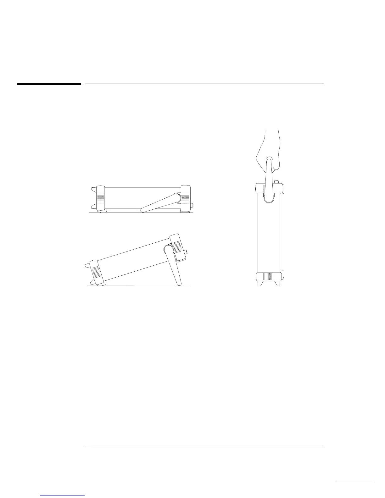
To Adjust the Carrying Handl
e
To adjust the
position, grasp
th
e han
dle by the sid
es and
pu
ll outwar
d
.
Then, rotate
the handle
to the desired p
osition.
Car
ry
ing P
ositi
on
Be
nch
top V
iew
ing
Posit
ion
s
Chapter 2
Quick Start
To
Ad
ju
st the Ca
rr
ying
Ha
nd
le
44
45
47
Table of Contents
Main Page
Default Chapter
12
Table of Contents
12
34905A/34906A RF Multiplexer Component Locator 257
16
Chapter 1 Specifications DC, Resistance, and Temperature Accuracy Specifications
18
DC Measurement and Operating Characteristics
19
AC Accuracy Specifications
20
AC Measurement and Operating Characteristics
21
Measurement Rates and System Characteristics
22
Module Specifications
23
Benchlink Data Logger Software Specifications
26
Product and Module Dimensions
27
To Calculate Total Measurement Error
28
Interpreting Internal DMM Specifications
30
Configuring for Highest Accuracy Measurements
33
Chapter 2 Quick Start to Prepare the Instrument for Use
37
To Connect Wiring to a Module
38
To Set the Time and Date
40
To Configure a Measurement Channel
41
To Monitor a Single Channel
42
To Close a Channel
43
If the Instrument Does Not Turn on
44
To Adjust the Carrying Handle
46
To Rack Mount the Instrument
47
Chapter 3 Front-Panel Overview Front-Panel Menu Reference
51
To Unsecure for Calibration
53
To Secure against Calibration
53
To Change the Security Code
54
Error Messages
54
To Perform a Zero Adjustment
55
To Apply MX+B Scaling to Measurements
56
To Read the Relay Cycle Count
57
To Read a Digital Input Port
58
To Write to a Digital Output Port
59
To Read the Totalizer Count
60
To Output a DC Voltage
61
Chapter 4 Calibration Procedures Agilent Technologies Calibration Services
65
Calibration Interval
65
Adjustment Is Recommended
65
Time Required for Calibration
66
Automating Calibration Procedures
66
Recommended Test Equipment
67
Input Connections
68
Calibration Security
69
To Unsecure the Instrument Without the Security Code
70
Calibration Message
71
Calibration Count
71
Calibration Procedure
72
Aborting a Calibration in Progress
72
Test Considerations
73
Performance Verification Tests
74
Self-Test
75
Quick Performance Check
76
Performance Verification Tests
76
Internal DMM Verification Tests
77
Zero Offset Verification
77
Gain Verification
79
Optional AC Performance Verification Tests
82
Internal DMM Adjustments
83
Zero Adjustment
83
Gain Adjustment
84
VDC Adjustment Procedure (Optional)
87
Plug-In Module Test Considerations
89
Relay Verification
90
Relay Cycle Count
90
34901A Relay Contact Resistance Verification (Optional)
91
34902A Relay Contact Resistance Verification (Optional)
98
34903A Relay Contact Resistance Verification (Optional)
103
34904A Relay Contact Resistance Verification (Optional)
104
34905A/06A Relay Contact Resistance Verification (Optional)
107
34908A Relay Contact Resistance Verification (Optional)
108
Thermocouple Reference Junction (Optional)
114
Thermocouple Reference Junction Verification
114
Thermocouple Reference Junction Adjustments
115
34907A Analog Output
116
Analog Output Verification Test
116
Analog Output Adjustment
117
Chapter 5 Theory of Operation
121
System Block Diagram
121
Floating Logic
122
Memory
125
Earth-Referenced Logic
126
Power Supplies
127
Front Panel
129
Backplane
130
Internal DMM
131
Input
132
Input Amplifier
133
Ohms Current Source
135
AC Circuit
136
A-To-D Converter
138
Switch Modules
140
Relay Drivers
142
A/34906A
150
Multifunction Module
153
Totalizer
155
Analog Output
156
Digital I/O
157
Chapter 6 Service
161
Operating Checklist
161
Types of Service Available
162
Repackaging for Shipment
163
Electrostatic Discharge (ESD) Precautions
164
To Replace the Power-Line Fuse
165
Unit Reports Error 705
166
Power Supplies
167
Self-Test Procedures
169
Self-Tests
170
Battery Check and Replacement
174
To Verify the Battery
175
Disassembly
176
General Disassembly
177
Internal DMM Disassembly
178
Plug-In Module Disassembly
181
Chapter 7 Replaceable Parts
184
Replaceable Parts
184
A Mainframe
185
Main PC Assembly (A1)
186
Front-Panel and Keyboard PC Assembly (A2)
191
Backplane PC Assembly (A3)
192
Internal DMM PC Assembly (A4)
193
Chapter 8 Schematics
198
A 20-Channel Multiplexer
198
A 16-Channel Multiplexer
202
A 20-Channel Actuator
204
A 4X8 Matrix
206
A/34906A RF Multiplexer
209
A Multifunction Module
211
A 40-Channel Multiplexer
215
Manufacturer's List
218
A2 Display and Keyboard Component Locator
230
A2 Display and Keyboard Schematic
231
34901A 20-Channel Multiplexer Component Locator
240
34902A 16-Channel Multiplexer Component Locator
246
34907A Multifunction Module Component Locator
262
34908A 40-Channel Multiplexer Component Locator
268
Other manuals for Agilent Technologies 34970A
Manual
24 pages
Quick Reference Guide
20 pages
Related product manuals
Agilent Technologies 34980A
349 pages

 Loading...

