34908A
Components in this discussion are located on the A1 circuit assembly
(34908-66501). The schematics are included in Chapter 8 starting on
page 267.
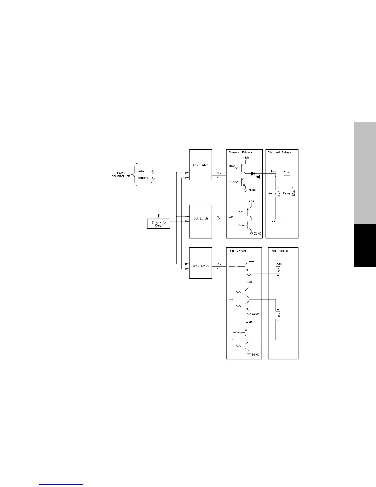
The control circuitry has three grouping of latches, relay drivers and
relays. The 40 voltage and resistance measurement channels are, for
control purposes, arranged into 8 rows by 10 columns. Tree switching
controls bank selection and connections to the analog bus.
The row latch, U102, and column latches, U103 and U104, control the
relays. The row drivers are divided into four groups of set and reset
drivers. Each group of row drivers controls five relays. The column
drivers operate as a pair. There are ten column drivers each
controlling two relays. The analog bus backplane relays are
non-latching.
Module Reference
5
Chapter 5 Theory of Operation
Switch Modules
149

 Loading...

