Tests 34 - 36: Close only channels Channels 20 and 22. Remove the 34901A from the
34970A and do not reinstall it for these tests.
On connector J101, remove the jumper between pins C14 and C15
(the top jumper shown in the diagram on page 91). On the remaining
jumper connected to J101 (the bottom jumper shown in the diagram),
move the end of the jumper from pin C12 to pin C16; the jumper
should now short pins C13 and C16 together.
Cut, but do not remove, the copper shorts on Channels 21 and 22
(the wires will be used for the 4-wire ohms measurements below).
Add a copper short between the L and H terminals on Channel 20.
Record the measured value as Test 34 in the table below.
Using the external DMM, make a 4-wire ohms measurement between
the L and I terminals on Channel 21. Record the measured value as
Test 35 in the table below.
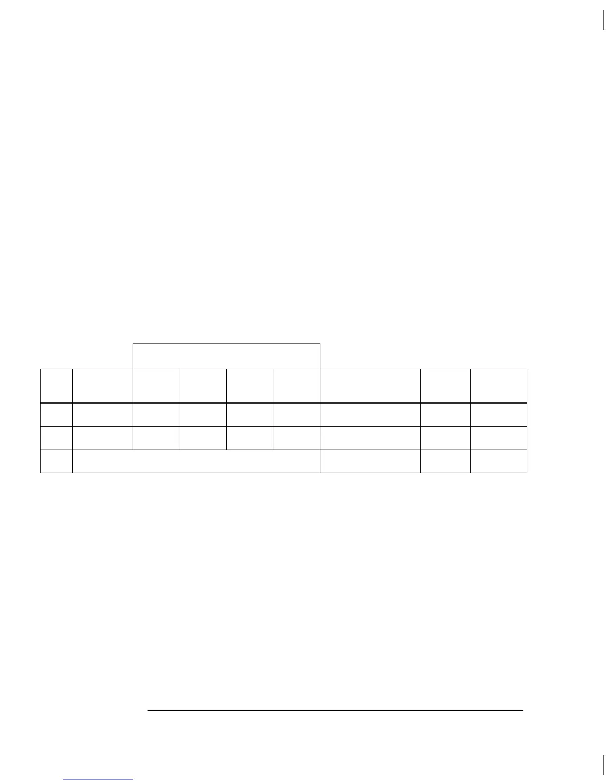
External DMM Ohmmeter Connections
Test
#
Channel
Closed
HI LO
HI
Sense
LO
Sense
Measured Value
Test
Limit
Relay
Measured
34 Ch 20* P3 P3 P2 P2 __________ Ohms
2.00Ω
K420
35 Ch 22*
Ch 21 I
Ch 21 L
Ch 21 I
Ch 21 L __________ Ohms — —
36 Subtract (Test 35 – Test 4) __________ Ohms
2.00Ω
K523
* The latching relays remain closed when the module is removed from the 34970A.
Chapter 4 Calibration Procedures
Relay Verification
94

 Loading...

