Chapter 3: Testing Performance
Analog Bandwidth - Maximum Frequency Check
3–21
11
Change the generator frequency to the maximum value for the model being tested as
shown in the table below. It is not necessary to adjust the signal amplitude at this point
in the procedure.
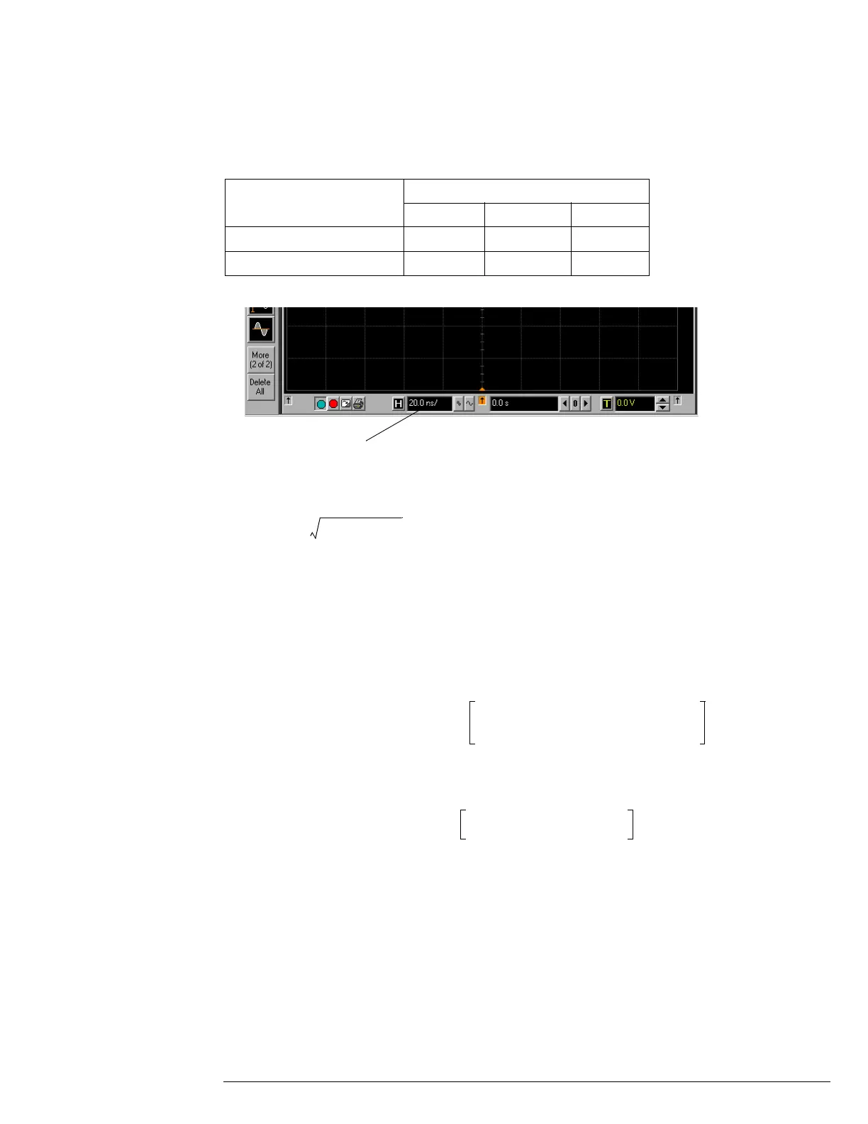
12 Change the scope time base to the value for the model under test in the table above.
13 Measure the input power to the scope channel at the maximum frequency and convert
this measurement to Volts RMS using the expression:
For example, if the power meter reading is 4.0 µW, then Vin = (4.0*10
-6
* 50Ω)
1/2
= 14.1 mVrms.
Record the RMS voltage in the Analog Bandwidth - Maximum Frequency Check section of the
Performance Test Record (Vin @ Max Freq).
14
Press the Clear Display key on the scope, wait for the #Avgs value (top left corner of
screen) to return to 16 and then record the scope V rms reading in the Analog
Bandwidth - Maximum Frequency Check section of the Performance Test Record (Vout
@ Max Freq).
15 Calculate the gain at the maximum frequency using the expression:
For example, if (Vout @ Max Frequency) = 13.825 mV, (Vin @ Max Frequency) = 13.461 mV and
Gain @ 50MHz = 1.0023, then:
Record this value in the Calculated Gain @Max Freq column in the Analog Bandwidth - Maximum
Frequency Check section of the Performance Test Record. To pass this test, this value must be
greater than -3.0 dB.
Setting Model
54853A 54854A 54855A
Maximum Frequency 2.5 GHz 4.0 GHz 6.0 GHz
Scope Time Base Setting 320 ps/div 200 ps/div 133 ps/div
Click here and enter time
base value from table
V
in
P
meas
50Ω×=
Gain
Max Freq
20 log
10
V
out Max Freq
()V
in Max Freq
()⁄
Gain
50 MHz
------------------------------------------------------------------------------------
=
Gain
Max Freq
20 log
10
13.825 mV 13.461 mV ⁄
1.0023
-------------------------------------------------------------
0.212 dB==