Chapter 5: Troubleshooting
To check probe power outputs
5–30
To check probe power outputs
3UREHSRZHURXWSXWVDUHRQWKHIURQWSDQHOVXUURXQGLQJHDFK%1&LQSXW
$Q\IDLOXUHPD\EHDSUREOHPZLWKWKHSUREHSRZHUDQGFRQWURODVVHPEO\WKH$XWR3UREH
IOH[FDEOH:WKHSUREHSRZHUDQGFRQWUROFDEOH:RUWKHSRZHUERDUG
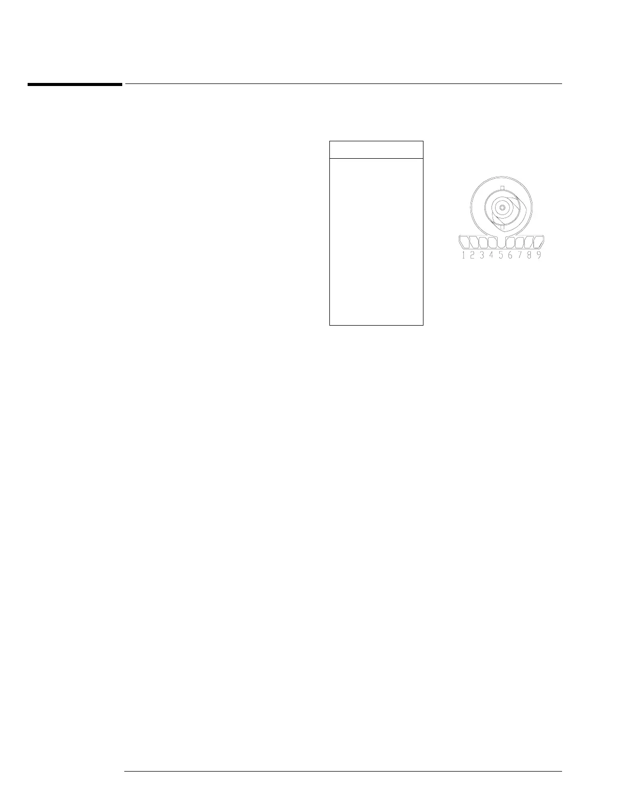
Use the table and figure to the right
to check the power output at the
connectors.
The +12 V and –12 V supplies
come from ripple regulator on
the power board, and the +3 V
and –3 V supplies are
developed in three-terminal
regulators on the probe power
& control assembly.
Measure the voltages with respect
to the ground terminal on the front
panel, located near the Aux Out
BNC.
Do not attempt to measure voltages
at pins 3 through 7.
Pin Supply
1+3V
2 –3V
3 Offset
4Data
5 &
ring
Probe ID
6Clk
7R
p
8 –12 V
9 +12 V