Chapter 6: Replacing Assemblies
To remove and replace the keyboard and flat-panel display assemblies
6–16
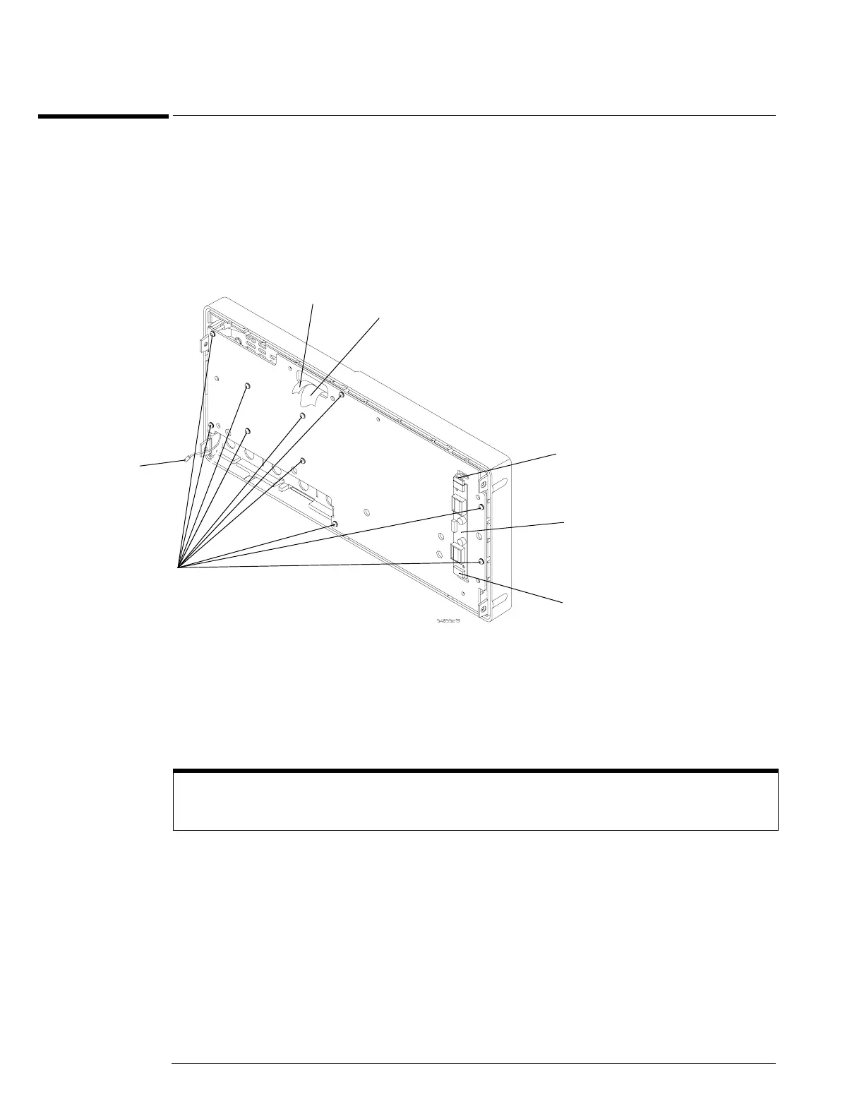
To remove and replace the keyboard and flat-panel display assemblies
Where necessary, refer to other removal procedures.
1 Disconnect the power cable and remove the cover.
2 Remove the front panel assembly from the chassis.
3 Remove the ten Torx T10 screws that secure the front panel cover plate to the front casting.
Figure 5-16
Front Panel Cover Plate Screws
4 Carefully feed the front-panel keyboard cable W12 and the flat-panel display driver cable
W11 through the cable access hole while separating the front panel cover plate from the
front casting.
Keep Long Screws Separate for Re-assembly
The four screws that fasten the keyboard to the front panel plate are longer than those around the perimeter
of the plate. Keep them separate for re-assembly.
Keyboard
Cable W12
Display
Cable W11
T10
Screws
(10)
Probe Comp
Wire
Backlight
Cable
Backlight
Cable
Backlight
Inverter
Board