Chapter 6: Replacing Assemblies
To remove and replace the covers
6–4
To remove and replace the covers
When necessary, refer to other removal procedures.
1 Disconnect the power cable.
2 Disconnect all scope probes and BNC input cables from the front panel.
3 Disconnect any other cables, such as mouse, keyboard, printer, or GPIB cables.
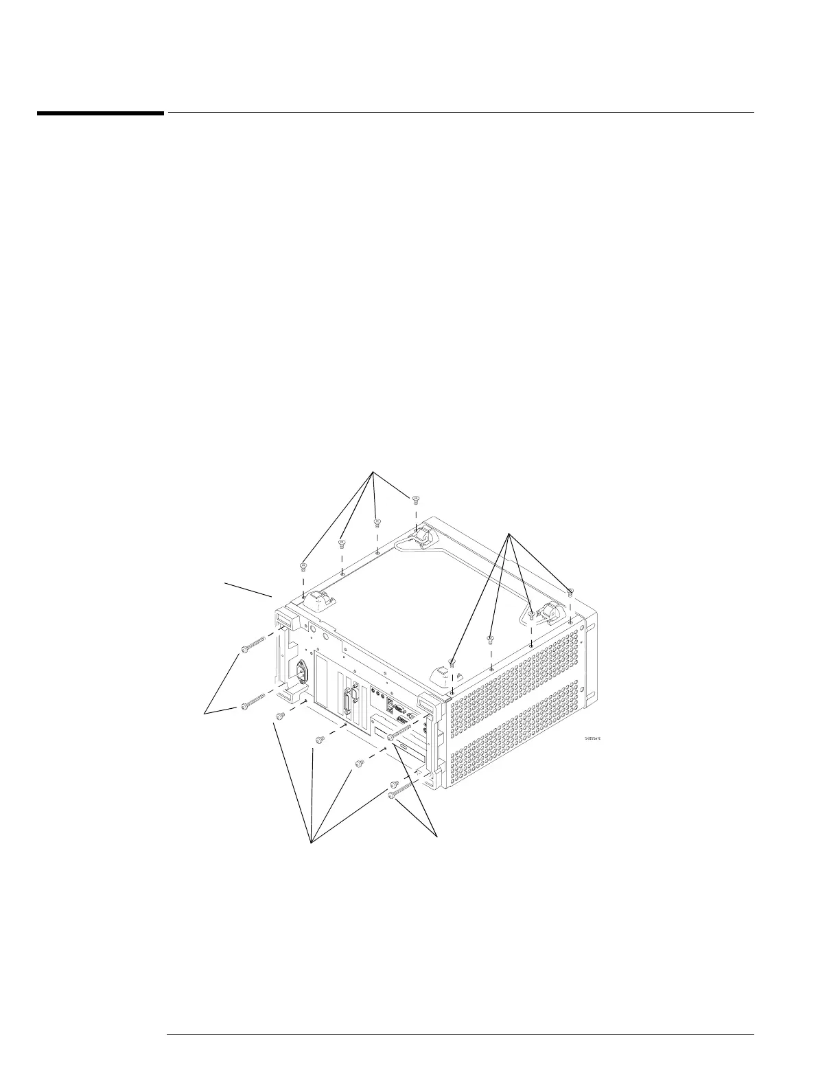
4 Remove the two Torx T15 screws securing the side handle.
5 Remove the four Torx T20 screws that secure the rear feet (two in each foot).
6 Remove the four Torx T20 screws that secure the top cover to the rear of the chassis.
7 Place the unit so the bottom is facing up.
8 Remove the eight Torx T10 screws that secure the top and bottom covers to the chassis.
9 Place the unit so the top is facing up.
10 Carefully slide the top cover off of the frame by pulling the front panel and the top cover
away from each other.
11 Place the unit so the bottom is facing up.
Figure 5-1
Fasteners to remove handle, rear feet, top cover
2 Handle
Screws
(Torx T15)
Torx
T10
Torx
T20
Torx
T10
Torx
T20
Torx
T20