Chapter 3: Testing Performance
Trigger Jitter Test
3–43
Trigger Jitter Test
Specification
Equipment Required
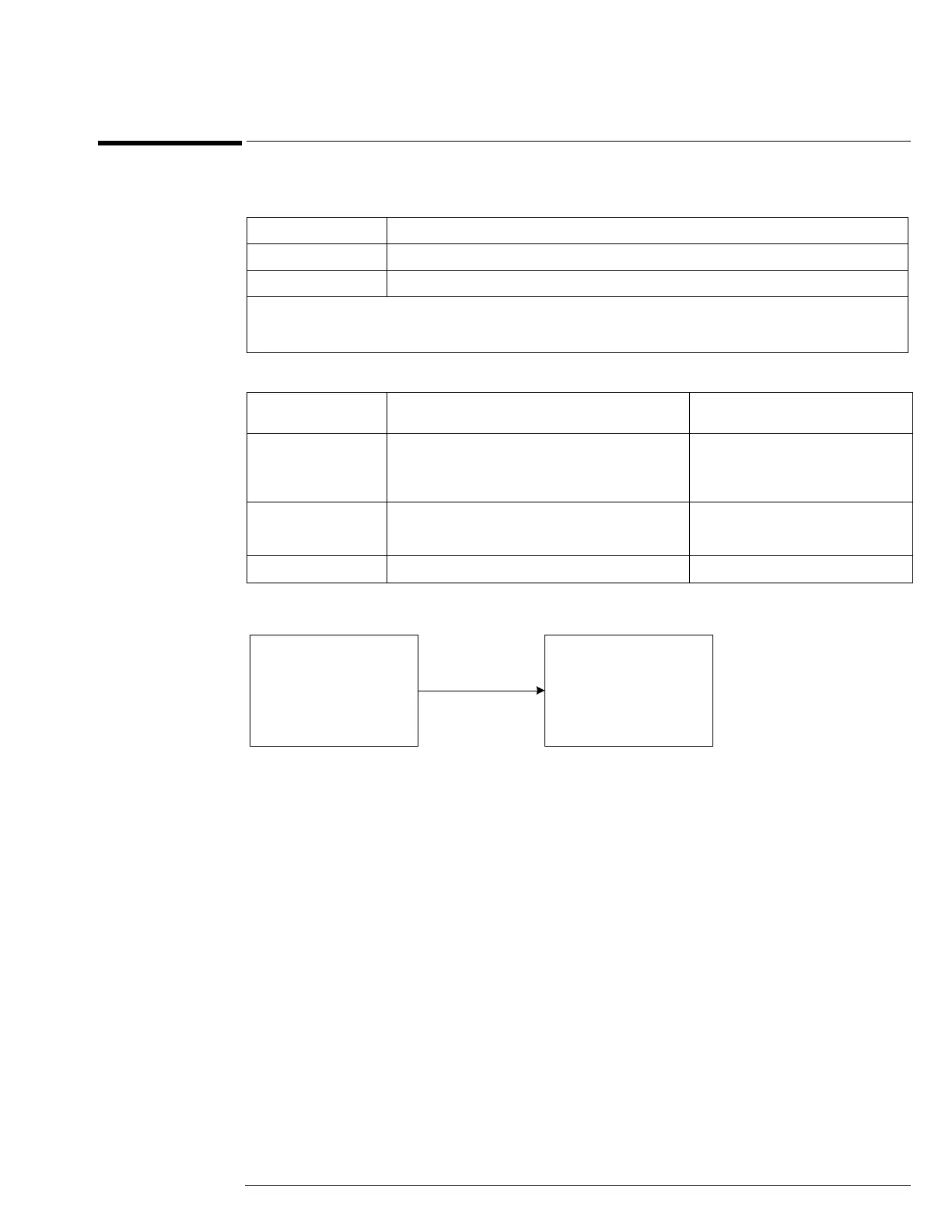
Connections
Procedure
1
Connect the microwave signal source to scope channel 1 as shown in the connection
diagram above.
2 Set up the source to operate as follows:
Frequency = 4 GHz (54855A and 54854A) or 2.5 GHz (54853A)
Amplitude = +10 dBm
54855A 1.0 ps rms
54854A 1.3 ps rms
54853A 1.7 ps rms
Signal peak-to-peak amplitude ≥5 divisions, vertical scale ≥10mV/div, signal rise time 155 ps (54853) ≤ 225 ps (54854) 150ps (54855),
sample rate = 20 GSa/s, sinx/x interpolation enabled, measurement threshold = fixed voltage at 50% level.
Internal trigger: Trigger level contained within full scale display range of trigger channel.
Description Critical Specifications Recommended Model/
Part Numbers
Microwave CW
Generator
Maximum Frequency ≥6 GHz
Power range: -20 dBm to +16 dBm into 50Ω
Frequency Accuracy better than 0.4 ppm
Output resistance = 50Ω
Agilent E8247C with Opt 520 or
Agilent 82712B with Opt 1E5 or
Agilent 8665B with Opt 004
Microwave Cable
Assembly
50Ω Characteristic Impedance
3.5 mm (m) or SMA (m) connectors
Max Frequency ≥18 GHz
Agilent 8120-4948 or
Agilent 11500E or
Gore EKD01D010480
Adapter 3.5 mm (f) to Precision BNC Agilent 54855-67604
Scope
Under
Test
Channel 1
Microwave
Signal
Source
50 Ohm
RF Output