27
Installation
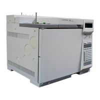
This chapter contains installation procedures for the GC. Most of the installation
steps apply to all GC systems—some are optional, such as plumbing for
cryogenic cooling and valve actuator air. Instructions are provided for
connecting cables from the GC to other instruments in a typical 6890 system. In
addition, information about configuring the GC and other instruments is
provided.
Most of installation involves plumbing gas to tanks, traps, and manifolds.
SWAGELOK™ fittings are used to make leak-tight connections. If you are not sure
how to make a
SWAGELOK connection, see Appendix A for instruction.
The installation steps assume you need less than 15 feet (4.6 m) of 1/8-inch gas
supply tubing for each gas source. For longer installations, use 1/4-inch tubing
and appropriate hardware and reducer fittings.
WARNING Hydrogen is a flammable gas. If hydrogen or any other flammable gas is used,
periodic leak tests should be performed. Be sure that the hydrogen supply is off
until all connections are made, and insure that the inlet fittings are either
connected to a column or capped at all times when hydrogen gas is present in
the instrument.
Substituting parts or performing any unauthorized modification to the
instrument may result in a safety hazard.
The insulation around the inlets, detectors, valve box, and the insulation cups is
made of refractory ceramic fibers (RCF). To avoid inhaling RCF particles, we
recommend these safety procedures: ventilate your work area; wear long
sleeves, gloves, safety glasses, and a disposable dust/mist respirator; dispose of
insulation in a sealed plastic bag; wash your hands with mild soap and cold water
after handling RCFs.
 Loading...
