7-47
Operating Concepts
Measurement Calibration
Two-Port Error Model (ES Models Only)
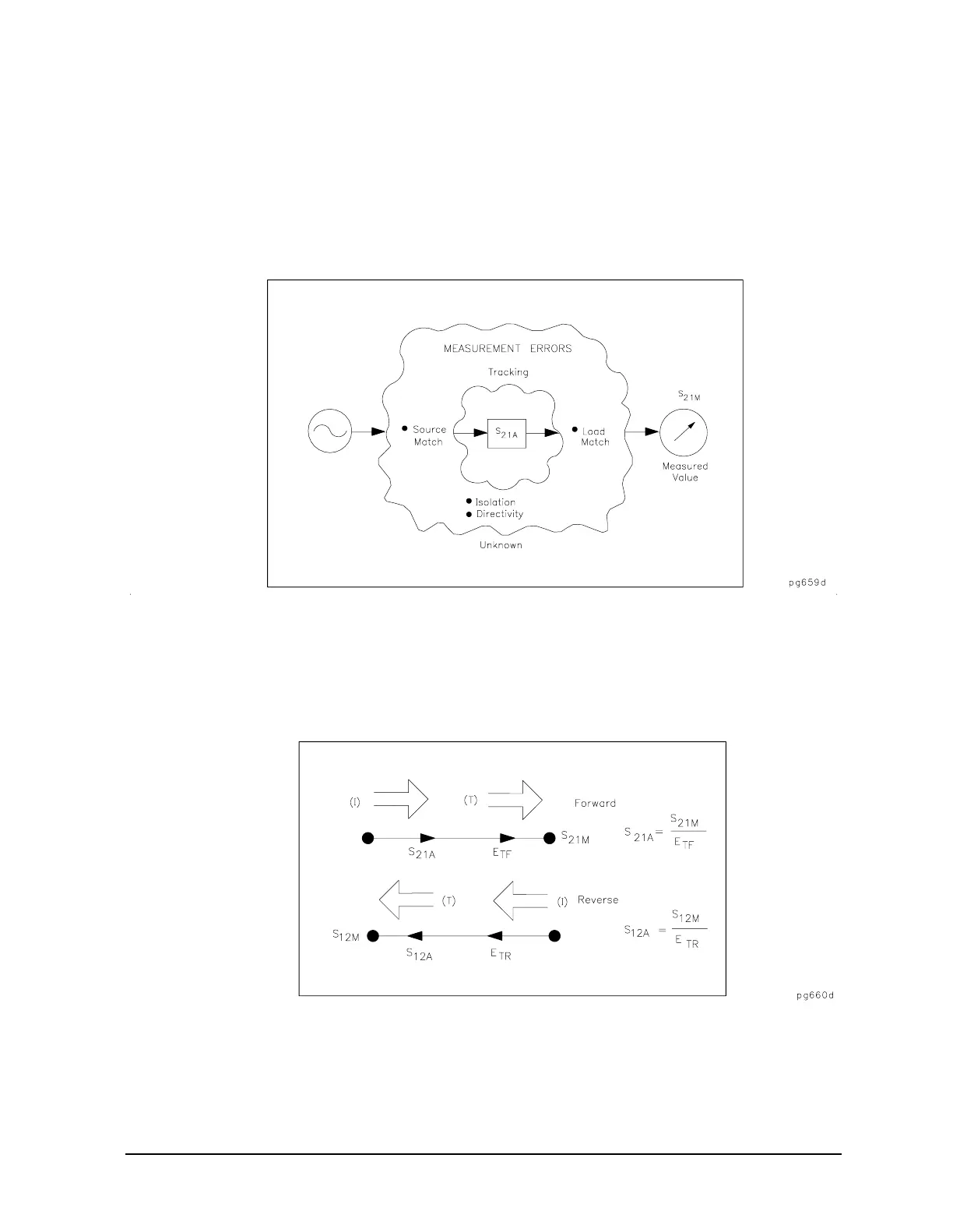
The error model for measurement of the transmission coefficients (magnitude and phase)
of a two-port device is derived in a similar manner. The potential sources of error are
frequency response (tracking), source match, load match, and isolation as shown in Figure
7-34. These errors are effectively removed using the full two-port error model.
Figure 7-34 Major Sources of Error
The transmission coefficient is measured by taking the ratio of the incident signal (I) and
the transmitted signal (T). Refer to Figure 7-35. Ideally, (I) consists only of power delivered
by the source, and (T) consists only of power emerging at the test device output.
Figure 7-35 Transmission Coefficient

 Loading...


