1-6
Troubleshooting the Analyzer
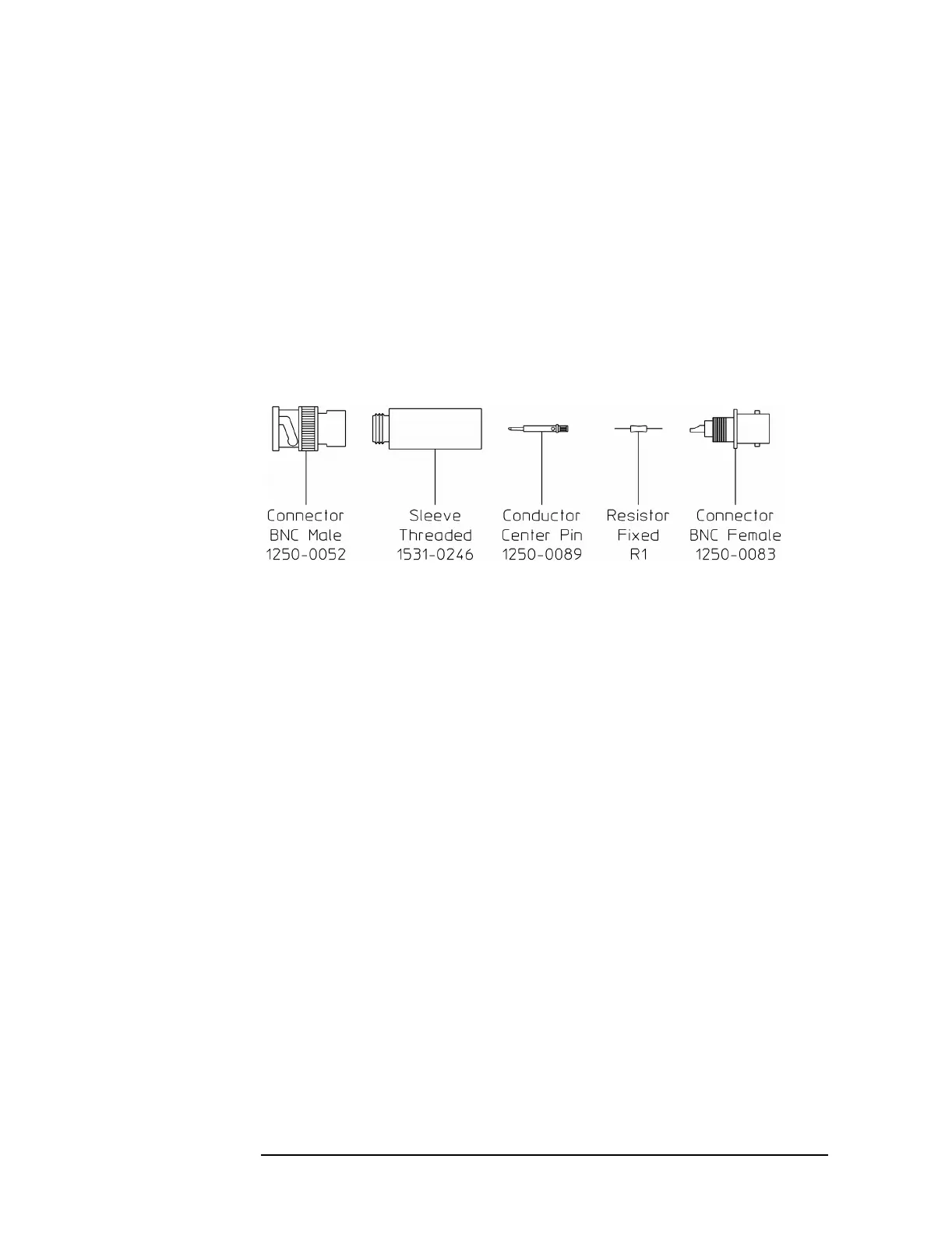
Suggested Assembly for Series Resistor
The following is a suggested assembly for the 10 kW series resistor. The
10 kΩ series resistor is required for the Input Offset adjustment.
1 Cut resistor leads to 12 mm on each end.
2 Solder one resistor lead to the center conductor of the BNC female
connector.
3 Solder the conductor center pin to the other lead of the resistor.
4 Screw the sleeve and the BNC male connector into place. Tighten
securely.
Troubleshooting Hints
● Check that the analyzer has the latest firmware before starting the
troubleshooting procedures.
● Incorrect bias supply voltages can cause false diagnostic messages.
Most troubleshooting procedures do not check the power supply
voltages through the motherboard. If you suspect incorrect supply
voltages to an assembly, use the ‘’A90/A91 Motherboard Voltages’’
table on page 6-24 and an extender board to check the voltages at the
assembly.
● The troubleshooting procedures do not isolate failures to cables or
connectors. If you suspect a cable or connector failure, check the
device for continuity.
● Cables can cause intermittent hardware failures.
● Noise or spikes in the power supply can cause the analyzer to fail.
● Measurements in this chapter are only approximate (usually ±1 dB or
10%) unless stated otherwise.
● Use chassis ground for all measurements in this chapter unless stated
otherwise.

 Loading...


