1-31
Troubleshooting the Analyzer
To troubleshoot display failures
e If this voltage is incorrect then the A82 assembly is probably
faulty.
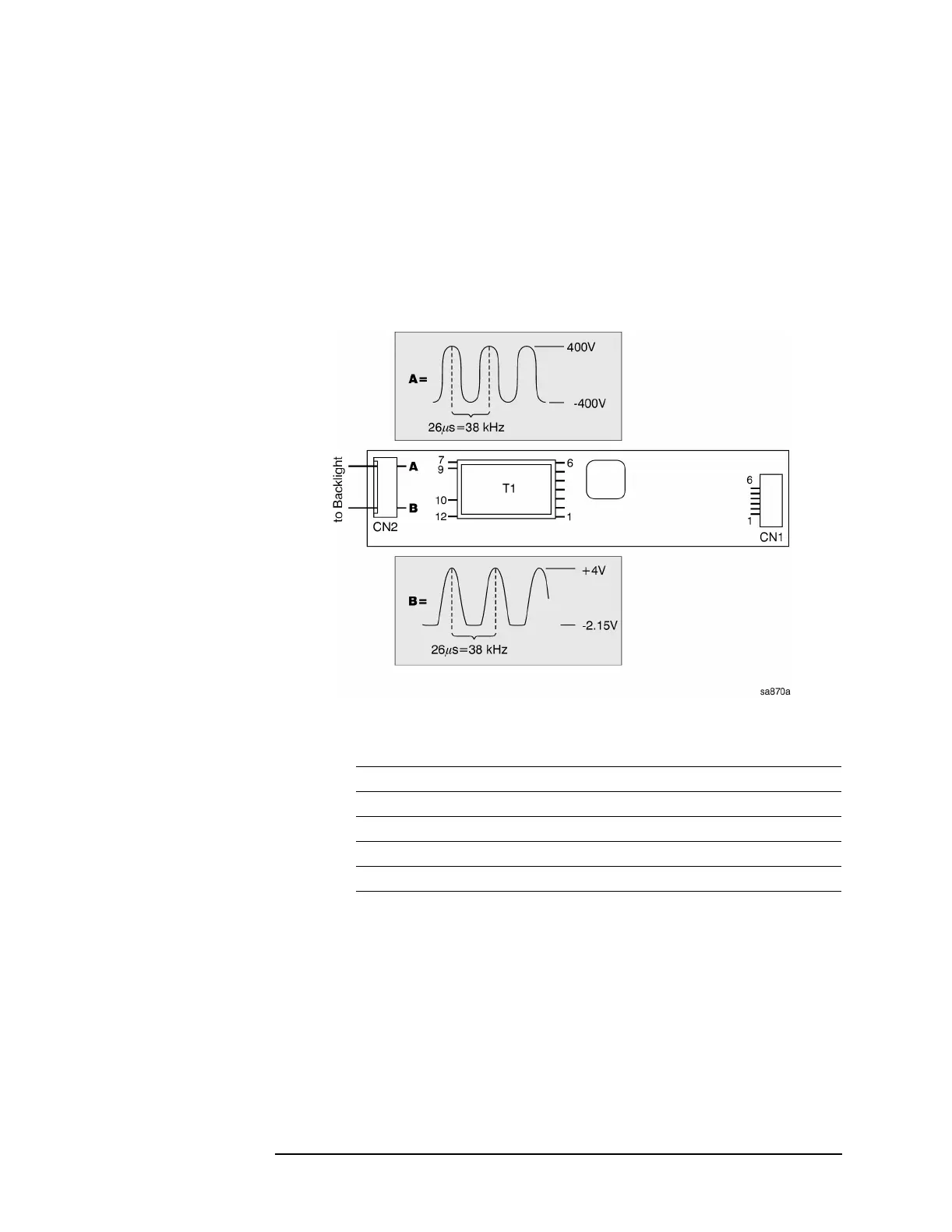
f Check the input and output signals of the inverter board as listed
below.
g If the inputs to the inverter are incorrect the cable is probably
faulty.
h If the outputs of the inverter are incorrect then the inverter is
probably faulty.
i If the outputs of the inverter are correct then the back light is
probably faulty.
Test Point Signal or Voltage
CN 1 pin 1 + 4.9 Vdc
CN 1 pin 2 + 4.9 Vdc
CN 1 pin 6 + 1.2 Vdc
CN 2 A − 400 V to + 400 V sinewave @ 38kHz (see figure)
CN 2 B − 2.15 V to + 4 V sinewave @ 38 kHz (see figure)

 Loading...


