152 Chapter 2
Front-Panel Key Reference
MEASURE
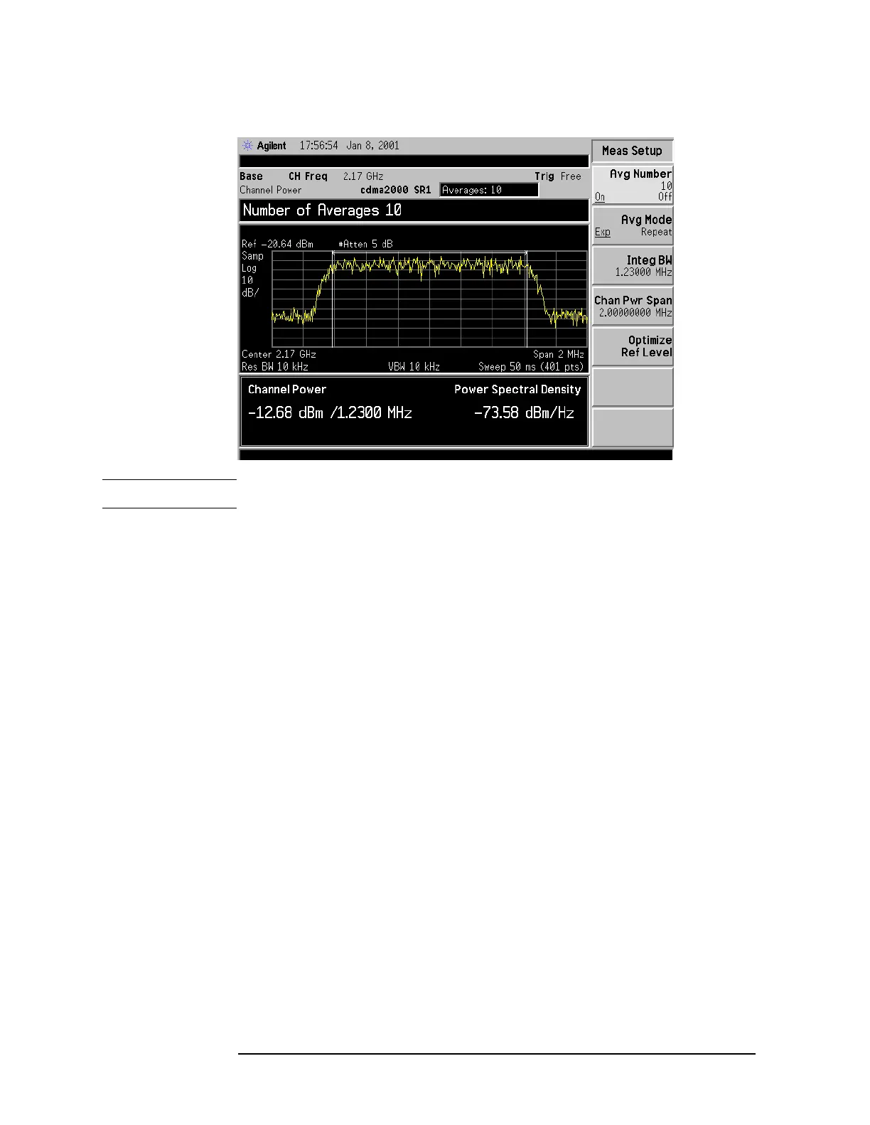
Figure 2-5 Channel Power Measurement Results
NOTE The displayed trace is the current trace, not the averaged trace.
Pressing
Meas Setup after Channel Power has been selected will access
the channel power measurement setup menu. Pressing
Radio Standard
after
Mode Setup has been selected will access all the Radio Standards
available for which this measurement can be applied (NADC MS,
excluded). Pressing
Meas Control after Channel Power has been selected
will access the channel power measurement control menu which allows
you to pause or restart your measurement, or toggle between
continuous and single measurement.
Key Access:
MEASURE
Occupied BW Integrates the power of the displayed spectrum and puts markers at the
frequencies between which the selected percentage of the power is
contained. (Refer to Figure 2-4 on page 130.) The measurement defaults
to 99% of the occupied bandwidth power. The power-bandwidth routine
first computes the combined power of all signal responses contained in
the trace. For 99% occupied power bandwidth, markers are placed at
the frequencies on either side of 99% of the power. 1% of the power is
evenly distributed outside the markers. The difference between the
marker frequencies is the 99% power bandwidth and is the value
displayed.
The occupied bandwidth function also indicates the difference between
the analyzer center frequency and the center frequency of the channel.
This difference is referred to as “Transmit Freq Error” in Figure 2-4 on
page 130.