Chapter 4: Testing Performance
Analog Bandwidth - Maximum Frequency Check
55
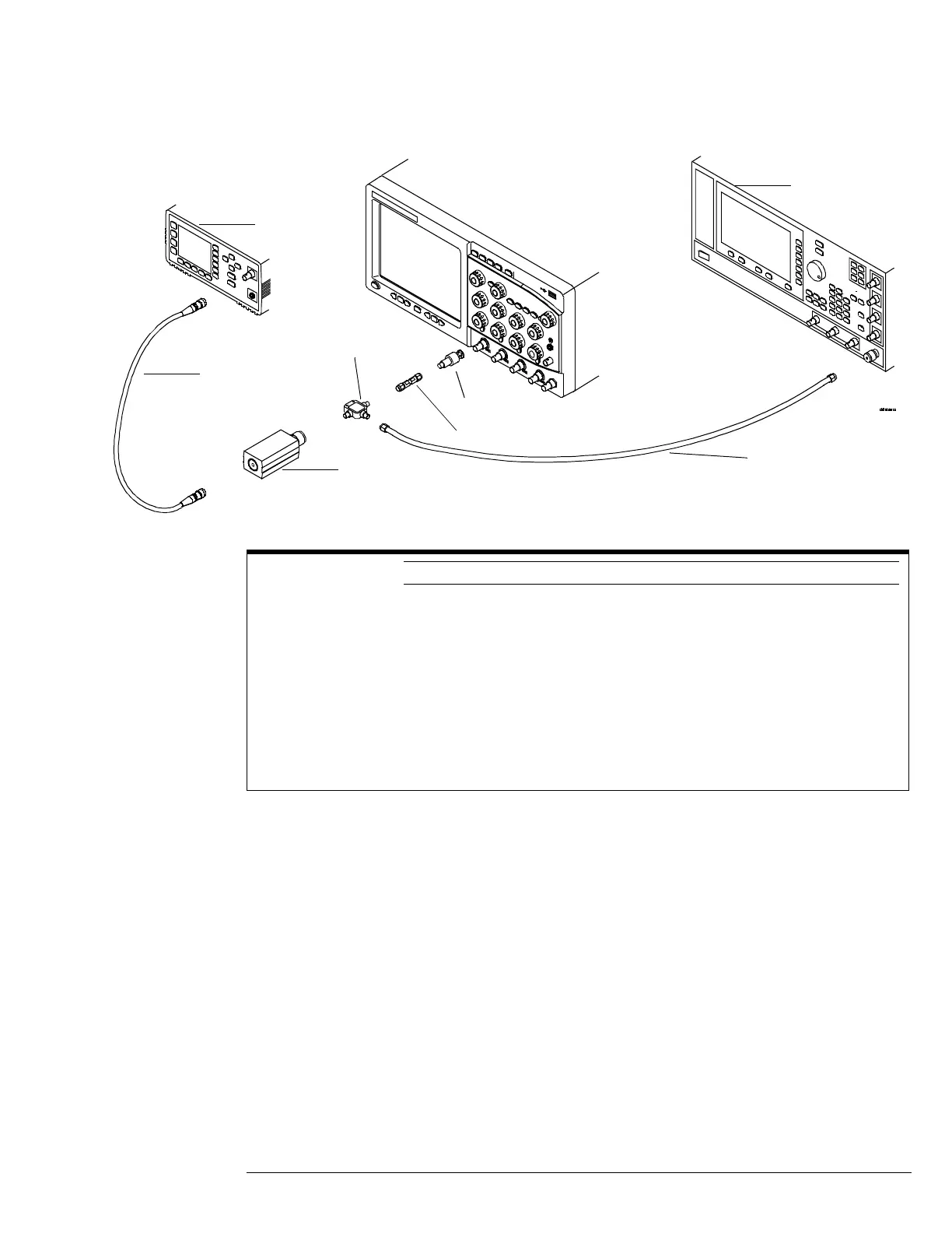
Connections
Procedure
1
Preset the power meter.
2 Ensure that the power sensor is disconnected from any source and zero the meter.
3 Connect the power sensor to the power meter's Power Ref connector and calibrate the
meter.
4 Make the connections to scope channel 1 as shown in the connection diagram above.
5 Set up the Power Meter to display measurements in units of Watts.
6 Press Default Setup, then configure the scope as follows:
a Ensure Channel 1 is displayed and all other channels are turned off.
b Set the vertical sensitivity of channel 1 to 5 mV/div.
Notes
• Connect output 1 of the 11667B splitter to the scope Channel n input directly using the 54855-67604
adapter, without any additional cabling or adapters.
• Connect the power sensor directly to output 2 of the power splitter without any additional cabling or
adapters.
• Minimize the use of other adapters.
• Ensure that SMA and 3.5 mm connectors are tightened properly:
8 in-lbs (90 N-cm) for 3.5 mm
5 in-lbs (56 N-cm) for SMA
Power sensor
cable
Power sensor
E4413A
Power splitter
11667B
SMA adapter
SMA to BNC adapter
Microwave cable
Microwave CW
Generator E8257D
Power meter
E4418A or
E4419A

 Loading...


