Chapter 4: Testing Performance
Analog Bandwidth - Maximum Frequency Check
57
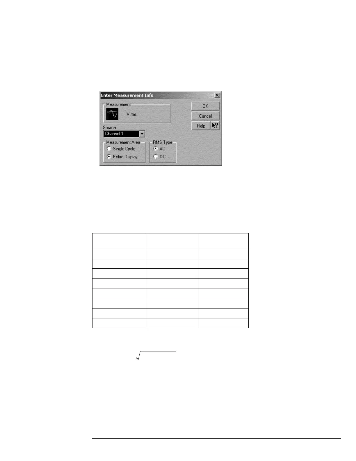
f When the RMS voltage measurement setup window is displayed, configure this
measurement as follows:
Source = Channel 1
Measurement Area = Entire Display
RMS Type = AC
7
Set the generator to apply a 50 MHz sine wave with a peak-to-peak amplitude of about
4 divisions.
• Use the following table to determine the approximate required signal amplitude.
The amplitude values in the table below are not absolutely required. If your generator is
unable to produce the recommended amplitude, then set the generator to the highest
value that does not produce a vertically clipped signal on the scope.
Table 3-1. Nominal Generator Amplitude Settings
8
Measure the input power to the scope channel and convert this measurement to Volts
RMS using the expression:
For example, if the power meter reading is 4.0 µW, then Vin = (4.0*10
-6
* 50Ω)
1/2
= 14.1 mVrms.
Record the RMS voltage in the Analog Bandwidth - Maximum Frequency Check section of the
Performance Test Record (Vin @ 50 MHz).
Scope
Vertical Sensitivity
Generator Signal
Amplitude (Vp-p)
Generator Signal
Amplitude (dBm)
5 mV/div 0.02 -30
10 mV/div 0.04 -24
20 mV/div 0.08 -18
50 mV/div 0.20 -10
100 mV/div 0.40 -4
200 mV/div 0.80 +2
500 mV/div 2.0 +10
1 V/div 4.0 +16
V
in
P
meas
50Ω×=

 Loading...


