Agilent N5161A/62A/81A/82A/83A MXG Signal Generators Service Guide
Troubleshooting
The Green Front Panel Power Switch LED or Yellow Standby LED is Not Working
1-59
f. See Figure 1-26. Use a voltmeter with a small probe to measure the output voltage +5.1V on the A6 DC-AC Inverter Interface
assembly at J1-34.
• If the voltage is within limits, the fault is likely with the A6 DC-AC Inverter Interface Board. Refer to
“A6 DC-AC Inverter Interface Board (N5181A/82A/83A)” on page 1-34 to troubleshoot.
• If the voltage is not within limits, measure J6-34 on the A3 RF assembly. Refer to Figure 1-25.
— If the voltage is within limits, replace W1.
— If the voltage is not within limits, go to step 4.
Figure 1-26 +5.1V on A6 at J1-34
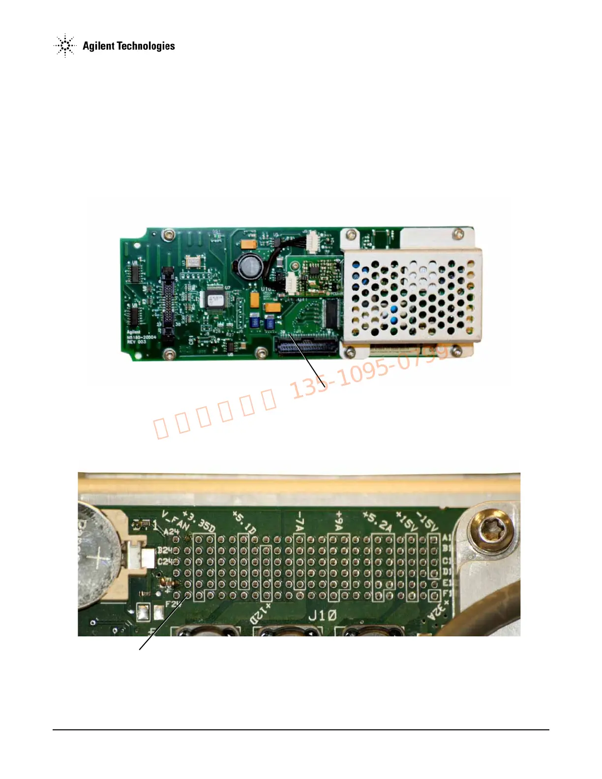
4. See Figure 1-27. Use a voltmeter with a small probe to measure the output voltage +5.1SB on the A3 RF assembly at J10-F23.
Figure 1-27 +5.1SB at J10-F23
• If the voltage is not within limits, the fault is likely with the A1 Power Supply. Replace the A1 Power Supply.
• If the voltage is within limits: