Agilent N5181A/82A MXG Signal Generators User’s Guide 9
Signal Generator Overview
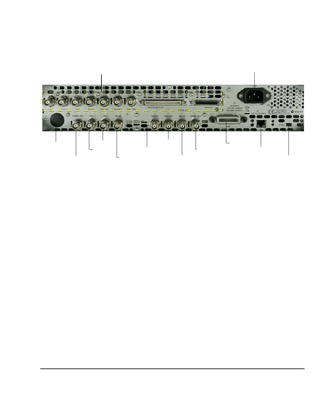
Rear Panel Overview
Rear Panel Overview
1. AC Power Receptacle
The AC power cord receptacle accepts a three- pronged AC power cord that is supplied with the
signal generator. For details on line setting requirements and the power cord, see the
Installation Guide.
2. SWEEP OUT
3. AM
Connector female BNC
Can drive 2 kΩ.
Impedance <1Ω
Signal Voltage range: 0 to +10V, regardless of sweep width
In swept mode: beginning of sweep = 0V; end of sweep = +10V
In CW mode: no output
This is a multiple use connector. For signal routing selections, see pages 33 and 57.
Connector female BNC Impedance nominally 50Ω
Signal An externally supplied ±1V
p
signal that produces the indicated depth.
Damage Levels 5V
rms
and 10V
p
2. SWEEP OUT
3. AM
4. FM
5. PULSE
6. TRIG IN
7. TRIG OUT
8. REF IN
10. GPIB
11. LAN
12. Device USB
9. 10 MHz OUT
Digital Modulation Connectors (vector models only) on page 12
1. AC Power Receptacle
Option 1EM
only
See page 5