EasyManuals Logo

Agilent Technologies n5181a User Manual

Agilent Technologies n5181a
175 pages
To Next Page IconTo Next Page
To Previous Page IconTo Previous Page
Page #97 background imageLoading...
Page #97 background image
86 Agilent N5181A/82A MXG Signal Generators User’s Guide
Basic Digital Operation (Option 651/652/654)
Using Waveform Markers
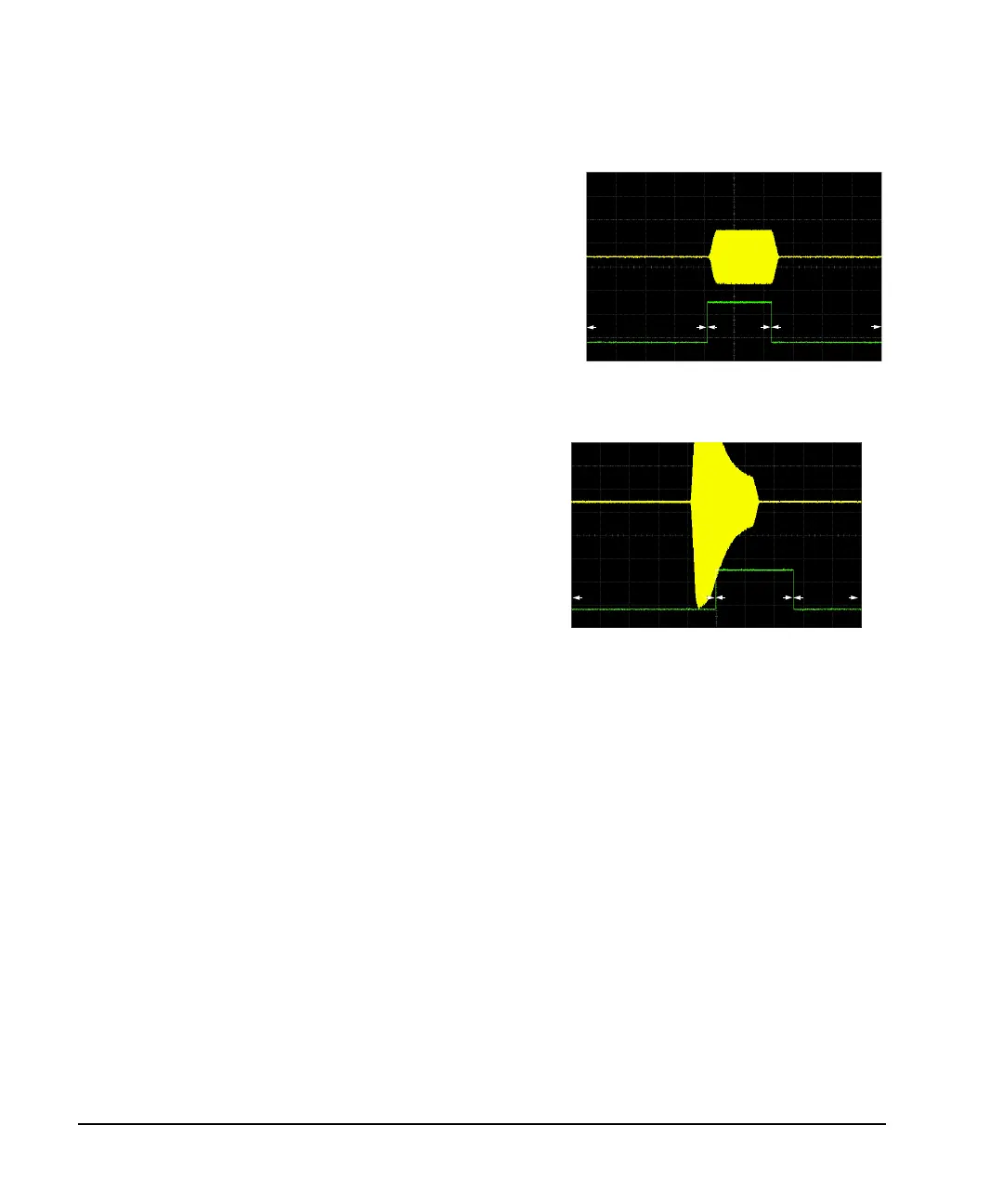
Sample range begins on first point of signa
l
Negative range set between signal and
off time
Example of Incorrect Use
Waveform: 1022 points
Marker range: 110-1022
Marker polarity: Negative
This figure shows that a negative polarity marker goes low during
the marker on points; the marker signal goes high during the off
points. The ALC samples the waveform during the off marker
points.
Marker On
Marker On
S
ampling both on and off time sets the modulator circuitry
i
ncorrectly for higher signal levels. Note the increased amplitude
a
t the beginning of the pulse.
Marker
Off
Marker On
Marker
Marker
Off
On

Table of Contents

Other manuals for Agilent Technologies n5181a

Questions and Answers:

Question and Answer IconNeed help?

Do you have a question about the Agilent Technologies n5181a and is the answer not in the manual?

Agilent Technologies n5181a Specifications

General IconGeneral
BrandAgilent Technologies
Modeln5181a
CategoryPortable Generator
LanguageEnglish

Related product manuals