4-8 Service Guide N5230-90014
Troubleshooting PNA Series Microwave Network Analyzers
Power Up Troubleshooting N5230A
Measure the Individual Voltage Supplies
WARNING
The instrument contains potentially hazardous voltages. Refer to the
safety symbols provided on the instrument and in “General Safety
Considerations” on page 1-3 before operating the unit with the cover
removed. Make sure that the safety instructions are strictly followed.
Failure to do so can result in personal injury or loss of life.
To measure the power supply voltages, it is necessary to remove the instrument’s outer
and inner covers. Refer to “Removing the Covers” on page 7-6 for removal procedures. Use
the E8356-60021 extender board to measure the individual power supply voltages. Insert
the extender board into an empty slot next to the A6 signal processing ADC module
(SPAM) board.
NOTE
If any one individual voltage supply from the A4 power supply develops an
over-voltage or over-current problem, all supplies are affected. The supply
goes into a “burp” mode characterized by the supplies cycling on and off at a
low voltage level. The cause of the over-voltage or over-current condition can
be the A4 power supply itself, or any assembly to which the A4 power supply
provides voltage. To isolate the cause of “burp” mode, continue to the
assembly removal process as described in the section titled “If All Supply
Voltages Are Missing” on page 4-9.
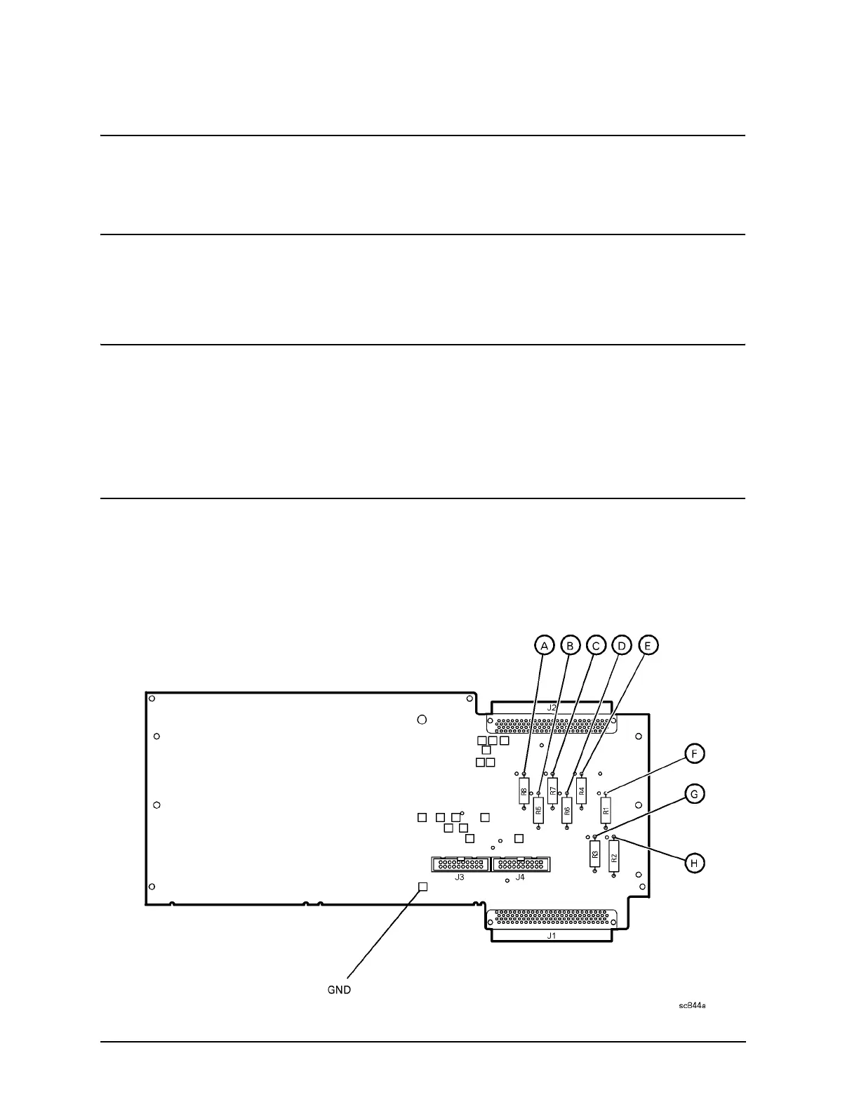
On the extender board, measure the power supply voltages using a digital multi-meter.
Refer to Figure 4-3 for the power supply test points on the extender board. Use the point
marked “GND” for the ground connection. Refer to Table 4-1 on page 4-9 for the correct
voltages.
Figure 4-3 E8356-60021 Synthesizer/Reference Extender Measurement Points