13
OVERVIEW
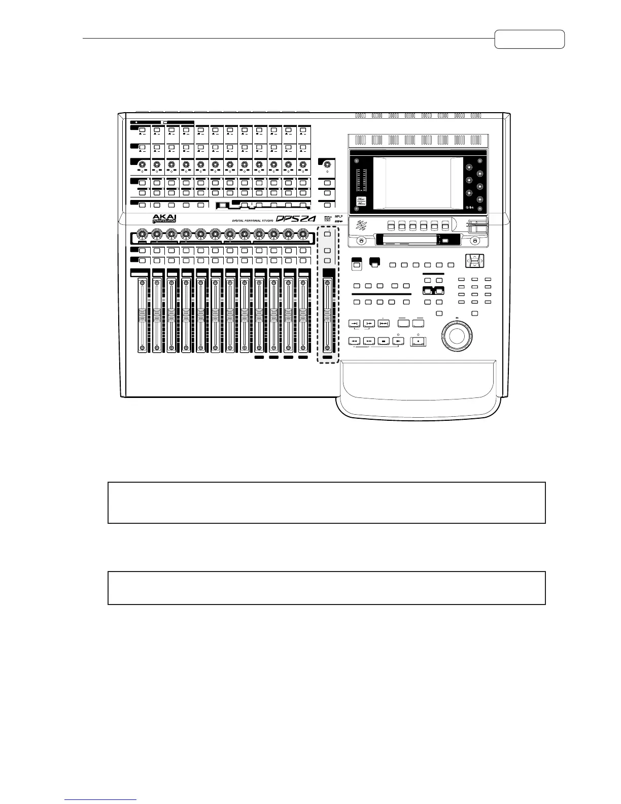
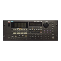
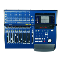
MASTER SECTION
To the right of the channel faders is the MASTER fader:
PRE PRE PRE PRE EQ ON
Q-CHANNEL
A B
LINE MIC
SIGNAL / CLIP
+60
0
!!SOLO!!
MAX
MIN
LINE MICLINE MICLINE MICLINE MICLINE MICLINE MICLINE MICLINE MICLINE MICLINE MICLINE MIC
A BA BA BA BA BA BA BA BA BA BA B
+60
0
+60
0
+60
0
+60
0
+60
0
+60
0
+60
0
+60
0
+60
0
+60
0
+60
0
SIGNAL / CLIP SIGNAL / CLIP SIGNAL / CLIP SIGNAL / CLIP SIGNAL / CLIP SIGNAL / CLIP SIGNAL / CLIP SIGNAL / CLIP SIGNAL / CLIP SIGNAL / CLIP SIGNAL / CLIP
+45
-15
+45
-15
+45
-15
+45
-15
+45
-15
+45
-15
+45
-15
+45
-15
+45
-15
+45
-15
TRIM
A / B
48V
LINE
/ MIC
ON OFF
ASSIGN
RECORD
/EDIT
SELECT
234567891011121
123456789101112
123456789101112
13 14 15 16 17 18 19 20 21 22 23 24
L / R 1 / 2 3 / 4 5 / 6 7 / 8
FX / AUX 1 FX / AUX 2 FX / AUX 3 FX / AUX 4
Q-STRIP
FUNCTION
PAN
MONITOR
LEVEL
2-TRACK
MONO
NEAR
+45
-15
+45
-15
34
78
812
456
4567
8123
23
567
1
TALK BACK
SELECT
STUDIO CR
GROUP 1 GROUP 2 GROUP 3 GROUP 4 GROUP 5 GROUP 6 GROUP 7 GROUP 8
SOLO SOLO SOLO SOLO SOLO SOLO SOLO SOLO SOLO SOLO SOLO SOLO
SELECT
ON
INPUT 1
TRACK 1 / 13
FX RTN 1 FX RTN 2 FX RTN 3 FX RTN 4 L / R
23456789101112
2 / 14 3 / 15 4 / 16 5 / 17 6 / 18 7 / 19 8 / 20 9 / 21 10 / 22 11 / 23 12 / 24
MASTER
PAN
LOW SWEEP
HIGH
EFFECT / AUX SENDS
L R
FX / AUX 1 FX / AUX 2 FX / AUX 3 FX / AUX 4
20Hz
-24dB
+24dB
20kHz
20Hz
-24dB
+24dB
20kHz
Q
20Hz
-24dB
+24dB
20kHz
ZOOM
V
.TRACK CD-RDSP PATCHGRID
SHIFT
OFFSET
ABORT
SET
LOOP
SETUPPROJECTFXAUTOMATEMIXEREDIT
CURSOR
789
456
123
-
+
0
OUT
JOG
@
SHUTTLE
RECALLSTORE
WHEEL
IN
INP MON
INP
1-12
TRACKS
1-12
TRACKS
13-24
GROUP
FX
USER
BANK
UNDO REDO PRE-ROLL AUTO
TO FROM IN OUT
AUTO LOCATE
OVER
REWIND FAST FORWARD STOP
5
5
MIX SCENE
ENTERCANCEL
FADER BANK
EXT
SYNC
MAIN
SCREEN
GO TO
MEMORY
TB
LEVEL
RELEASE
LOCK
CONTRAST
Q 1
Q 3
Q 5
Q 2
Q 4
Q 6
F 1 F 2 F 3 F 4 F 5 F 6
LR
2
0
6
4
10
8
20
15
25
35
30
40
60
50
CLIP
@
DISPLAY
@
SELECT
HOURS MINS SECS FRAMES
BARS BEATS CLOCKS
The MASTER section also has a long throw, touch sensitive, motorised fader. By default, this controls the stereo L/
R bus which, by default, appears at the STEREO OUT.
➸
NOTE :
Due to the DPS24’s flexible patching system, it is possible to route audio sources other than the L/R
bus to the STEREO L/R output. If another audio source is patched to the STEREO output, the MASTER fader
will not affect that audio source’s level.
Above the fader is a TALKBACK switch. This routes the internal talkback mic to the STUDIO outputs so that the
engineer in the control room can talk to the ‘talent’ in a separate studio area. The key is a ‘press-to-make’ switch that
needs to be held down for the talkback mic to be routed to the STUDIO outputs.
➸
NOTE :
To facilitate this, the AUX 3/4 sends need to be configured to be sent to the STUDIO L/R outputs.
This is set in the MIXER - FX/AUX SETUP page.
The illuminated SELECT key allows you to select the master channel for editing.
The illuminated STUDIO > CR key allows you to route the mix created on AUX 3 and 4 to the monitor output
feeding the control room’s monitoring system. In this way, it is possible for the control room engineer to set the mix
up very conveniently on the control room’s speakers.
The TALKBACK and STUDIO outputs are explained later in this operator’s manual.