•
- +A - +
Jru.
THR
RUO
PIT
ELE
AIL
Battery
ELE
PIT
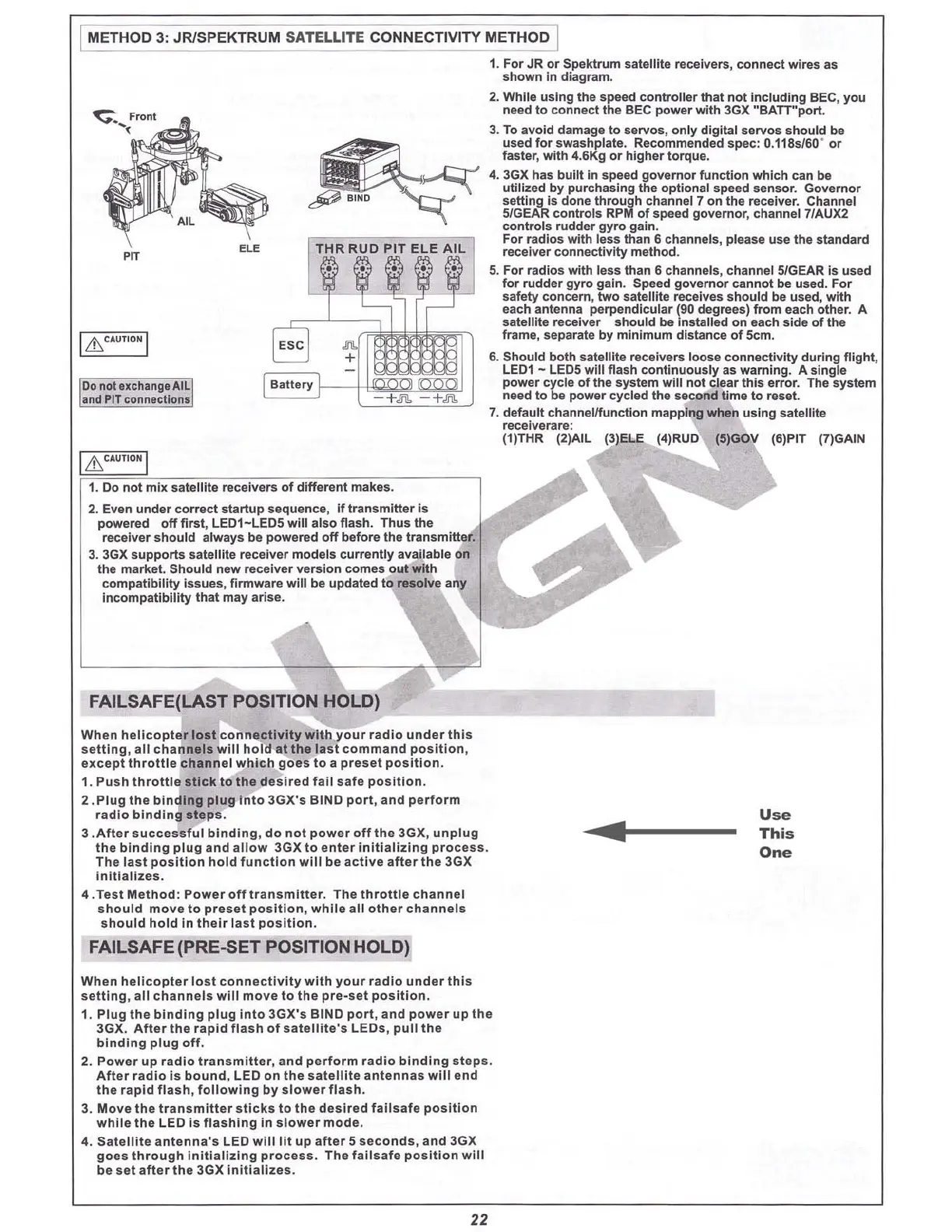
Donot uchangeAIL
Ind
PITconnecti
on.
1. Do not
mix
satellite receivers
of
different makes .
2. Even
under
correct
startup
sequence, If
transmitter
Is
powered
off
first, LE01- LE05 will also flash.
Thus
the
receiver should always be powered
off
before the
transmitter
.
3. 3GX
supports
satellite receiver mod els currently available on
the market. Should new recei
ver
version comes
out
with
compatibility
issues
, firmware
will
be updated to resolve any
in
compatibility
that
may arise.
[ Lh.CAUT IONI
I
METHOD
3:
JRlSPEKTRUM
SATELLITE
CONNECTIVITY
METHOD
I
1. For JR or Spektrum satellite receivers, connect wires as
shown in diagram.
2. While using the speed
controller
that
not
Including BEC, you
need to connect the BEC
pow
er
with
3GX "BATT
"port
.
3. To
avo
id damage to servos, only digital servos
should
be
used
for
swashplate. Recommended spec : O.118
sJ60
'
or
faster,
with
4.6Kg or higher torque.
4. 3GX has
built
in speed
gov
ernor function which can be
utilized by purchasing the optional speed sensor. Gov
ernor
setting is done through channel 7 on the receiver. Channel
51GEAR
controls RPM
of
speed governor, channel 7/AUX2
controls rudder
gyro
gain.
For radios with less than 6 channels, please use the standard
receiver conn ectiv
ity
method
.
5. For radios with less than
6 channels, channel 5/GEAR is used
for rudder
gyro
gain. Speed
governor
cannot be used. For
safety concern, two satellite receives
should
be used,
with
each antenna perpendicular
(gO
degrees)
from
each
other
. A
satellite receiver should be installed on each side
of
the
frame, separate by
minimum
distance
of
SCm
.
6. Should
both
satel1ite recei vers loose connectivity during fl
ight
,
LE01 - LEOS
will
flash
continuously
as warning. A single
power
cycle
of
the system
will
not
clear
thi
s
error
. The system
need to be power cycled the second time to reset.
7. default channel/function mapping when us
ing
satellite
recelve rare:
(1)THR (2)AIL (3)ELE (4)RUO
I
&CA
UTIONI
FAILSAFE([AST
POSITION HOLD)
When
helicopter
lost
connectivity
with
your
radio
under
thi
s
se
tti
ng,
all
channels
will
hold
at
the
la
st
command
po
sit
ion
,
ex.cept
thrott
le
channe
l
which
goes
to a
preset
po
sition
.
1.
Push
throtti
e
stick
to
the
desired
fall
safe
po
sition
.
2 .
Plug
th e b
inding
plug
Into
3GX's
BIND
port
,
and
perform
r
adio
binding
steps
.
3 .A
fte
r
successfu
l
binding,
do
not
power
off
the
3GX,
unplug
the
binding
plug
and
allow
3GX to
enter
initializing
proces
s.
The
la
st
position
ho ld
fun
ction
will
be act iv e
after
the
3GX
In
itializes
.
4 .T
est
M
ethod
:
Power
off
t ransm i
tte
r. The th
rottle
channel
should
mov
e
to
pre
set po
sition
,
while
all
oth
er
channe
ls
should
hold
In
their
last
po
sition
.
......f----
Use
This
One
FAILSAFE(PRE-5ET POSITION HOLD)
When
h
eli
copter
los
t
connecti
vity
with
your
radio
under
thi
s
setting
,
all
channels
will
mo
ve
to
th e p
re-s
et
position
.
1.
Plug
the
binding
plug
Int
o 3GX's BIND
port
, and
power
up th e
3GX,
After
the
rapid
flash
of
sate
lli
te's LEO s,
pull
t he
binding
plug
off
.
2.
Pow
er
up
radio
transm
itt
er,
and
p
erform
radio
b
inding
s
teps
.
After
radio
is
bound
, LED
on
the
sate ll
it
e
ant
enn
as
wlll
end
th e r
apid
flash,
following
by slowe r
flash
.
3.
Move
the
tran
smitter
sticks
to
the
de
sired
fa
ilsafe
p
osition
while
the LED
is
flashing
In
slower
mode
.
4. Sat
ellite
ant
enna
's LED
will
lit
up
after
5 seconds,
and
3GX
goes
through
initializing
proc
ess
. The
failsaf
e
po
sition
will
be
set
after
the
3GX Init ia
li
zes .
22