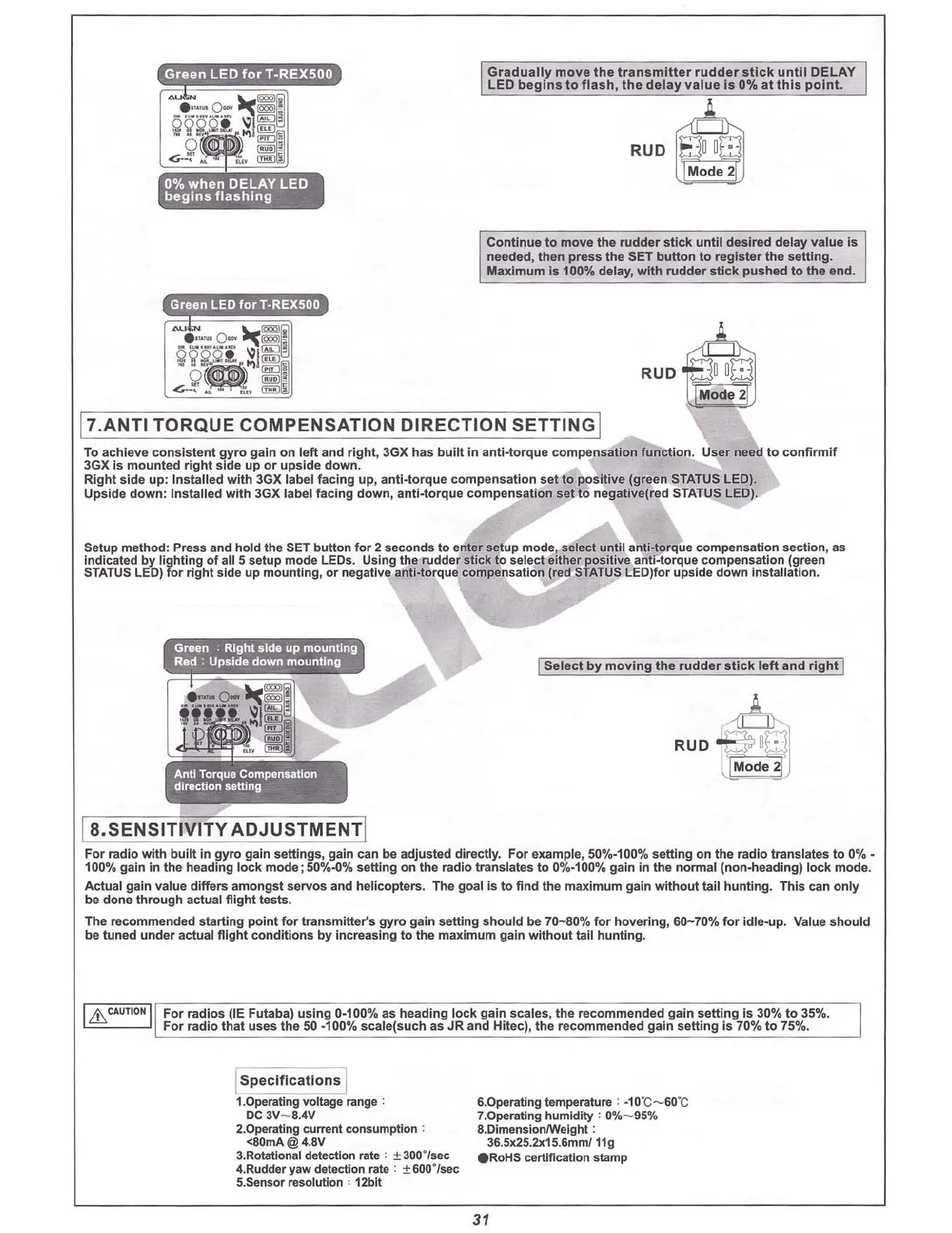
IGradua
lly
move the tra
nsmitte
r rudder
stick
u
ntil
DELAY I
I LED beg
ins
to f
las
h,
the
delay va
lue
Is 0% at
this
p
oint.
J,
,,,
RUD 8 u
o·
Mode 2
Cont
inue to
move
the
rud
der
stick
u
nt
il desired
delay
value
is
needed,
then
press
the
SET
button
to regis
ter
the
setting.
Maximum
is 100%
delay
,
with
rudde
r
stick
pus
hed
to
the
end.
Green
LED
for
T·REX500
17.ANTI TORQUE COMPENSATION DIRECTION SETTINGI
RUD
•
To a
chieve
consistent
gyr
o gain
on
l
eft
and r
ight,
3GX
has
b
ui
lt in an
ti-to
rque
compensa
tio
n
function
. User need to
confirmif
3GXIs mounted right side up or upside down.
Right
side
up
:
Insta
lled
with
3GX label
facing
up, an
ti-
torque
co
mpensation
set
to
positive
(green STATUS LED).
Upside
dow
n:
Installed
with
3GX label
faci
ng d
own
,
ant
i-torque
compensation
set to
negat
ive(red
STATUS LED).
Setup method: Press and hold the SET
button
for 2 seconds to enter setup mode, select un
til
anti-torque co
mpensation
section
, as
indicated by light ing of all 5 setup
mode
LEOs. Using th e rudder
stick
to
select
either pos itive anti-torque
compensatio
n (green
STATUS LED) for rig ht
side
up
mou
nting
, or negative a
nti-to
rque compensation (red STATUS LED)for upside
down
insta
llation.
Antl Torque
Compenullon
dll1lctlon 8ettlng
I
Select
by
mo
v
in
g the
rudder
sti
ck
le
ft
and righ t I
l a.SENSITIVITY ADJUSTMENTI
F
or
radio
with
built
in
gy
ro gain
settings
, gain can be adjusted
directly
. For example, 50%·100%
setting
on the ra
di
o tra nslates to 0
%-
100
'"1
. gain in the heading lock
mode
;50%.()%
setting
on the radio translates to 0%-100%
gain
in the
nonna
l (
non-hea
dlng)
lock
mo
de.
Act
ual gain val ue differs
amongst
servos
and
helicopters
. The goal Is
to
find the
max
imum
gain wi t
hout
tail hunt
in
g. This can
only
be done
thr
ough actual flig
ht
tests
.
The
reco
m
men
ded
start
ing point fo r tra
nsm
itter's gyro gain setting s
hould
be
7
0-80
% for hovering,
60-
70% for
idl
e-up. Value s
hou
ld
be tuned
und
er actual fli
ght
co
nditions by increasing
to
the maximum gain
wit
hout
tail hunt ing.
I
Lb.
CAUTION I
For
radios
(IE Futaba)
using
0-100% as
heading
l
ock
gain
scale
s, the
recommende
d gai n
setting
Is 30% to 35%.
For
radio
that
uses
th e 50 ·100%
scale(such
as JR and Hitec), the
recommended
gain
setting
is 70% to 75%.
Is pe
Ci
ficatio
'iij
1.0peratlng voltage range :
DC 3V
-8
.4V
2.0peratlng current consumption ;
<80mA@ 4.8V
3.Rotational detection rate : ± 300·/sec
4.Rudcler 'law detection rate : ± 800·ls
e<:
5.Sensor resolution ' 12blt
6.0perating temperature : ·10"C- 60"C
7.0perating humidity : 0%
-95
%
8.DimensioruWeighl :
36.5K25.2x15.8mm/ 11g
eRo
HS certification stamp
31