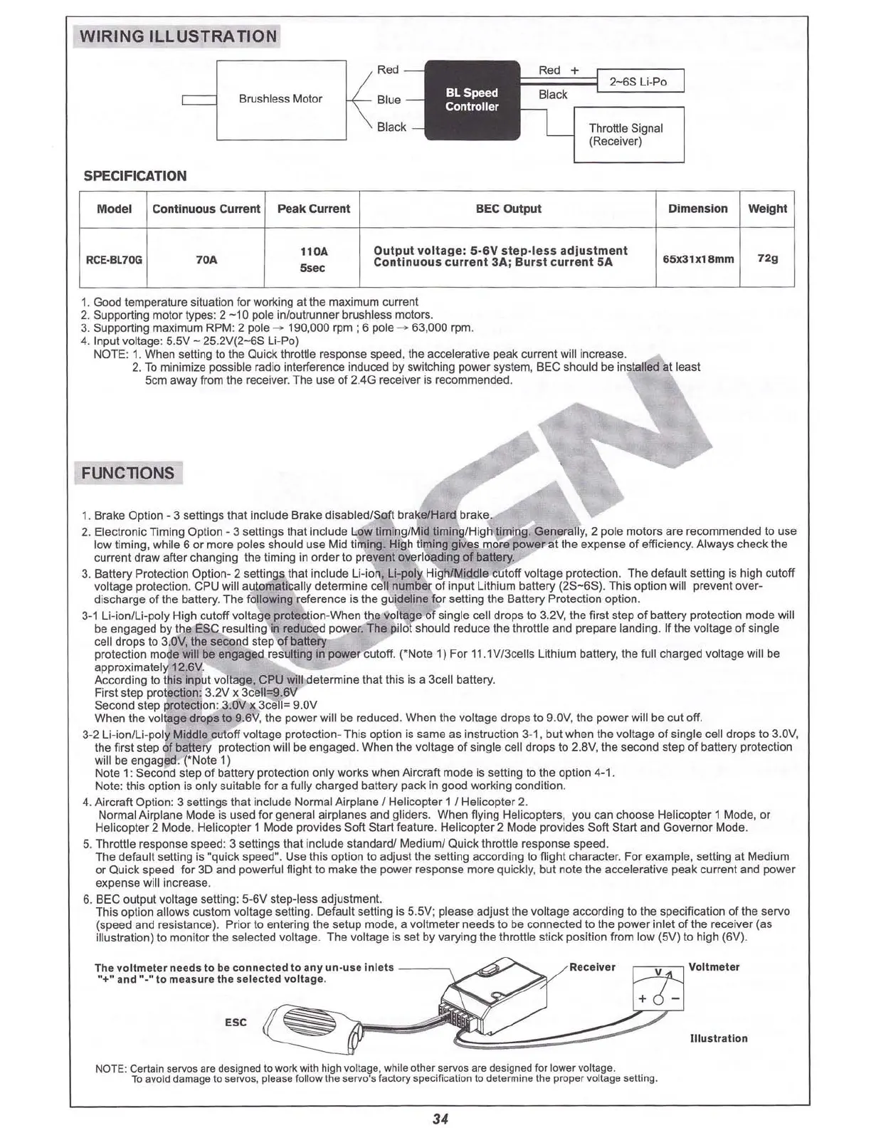
WIRING
ILLUSTRAT
ION
Brushless
Motor
2-65
Li·Po
Throttle Signal
(Receiver)
SPECIFICATION
M
odel
Continuous Current Peak Current
BEC Output Dimension Weight
RCE·BL7
OG
70A
110A
5
.
~
Output
v
olt
age :
5-6V
st ep -tes s adj ust me
nt
ContInuous cu rrent 3Aj Burst
curr
ent sA
6Sx31x18mm 72g
1. Good lemperature situation for working at the maximum current
2. Supporting motor types: 2
-10
pole inJouttunner brushless motors.
3. Supporting maximum RPM: 2 pole
--
190,000 rpm : 6 pole ---> 63,000 rpm.
4. Input voltage:
5.5V
- 25
.2V(2-£S
Ll-Pc]
NOTE
: 1. When setting to the Quick throttle response speed, the accelerative peak current will increase.
2. To minimize possible radio interference induced by switching power system. BEC should be instatle1fat least
Scm away from the receiver. The use of 2.4G receiver is recommended.
FUNCllONS
1. Brake Option - 3 settings that include Brake disabled/
Soft
brake/Hard brake
2. Electronic Timing Option - 3 settings that include Low timing/Mid liming/High liming. Generally, 2 pole motors are recommended to use
low timing, while Sor more poles should use Mid timing. High timing gives more power at the expense of efficiency. Always check the
current draw after changing the timing in order to prevent overloading of battery
3. Battery Protection Option- 2 settings that include
li
-ion, U-poly High/Middle cutoff volt age protection. The default setting is high cutoff
voltage protection. CPU will automatically determine cell number of input
lith
ium battery
(2S-SS)
. This option will prevent over-
discharge of the battery. The following reference is the guideline for setting the Battery Protection option.
3·1 U-ionILi-poly High cutoff volta ge protection-When the voltage of single cell drops to 3.2V
.t
he first step of ba
ll
ery protection mode will
be engaged by the ESC resulting in reduced power. The pilot should reduce the throllie and prepare landing. If the voltage of single
cell drops to 3.0V, the second step of battery
protection mode will be engaged resulting in
PQ
wer cutoff. (-Note 1) For 11.1V/3cells Lithium battery. the full charged voltage will be
approximately 12.6V.
According to this input voltage. CPU WIll determine that this is a 3cell battery.
First step protection: 3.2V x 3cell=9.6V
Second step protection: 3.0V x 3cell= 9.0V
When the voltage drops to 9.SV, the power will be reduced. When the voltage drops to 9.0V. the power will be cut off.
3-2
li
-ion/Li-poly Middle cutoff voltage prctactlon- This option is same as instruction 3-1. but when the voltage of single cell drops to 3.0V,
the first step of batte ry protection will be engaged. When the voltage of single cell drops to 2.8V, the second step of battery protection
will be engaged.
(·No
te 1)
Note 1: Second step of ballery protection
only
works when Aircraft mode is setti ng to the option 4-1.
Note: this option is only suitable for a fully charged battery pack in good working condition.
4. Aircraft Option: 3 settings that include Normal Airplane / Helicopter 1 / Helicopter 2.
Normal Airplane Mode is used for gen eral airplanes and gliders . When flying Helicopters, you can choos e Helicopter 1 Mode, or
Helicopter 2 Mode. Helicopter 1 Mode provides Soft Start feature. Helicopter 2 Mode provides
Soft
Start and Governor Mode.
5. Throttle respo nse speed: 3 settings that include standard/ Medium/ Quick throttle response speed .
The default setting is "quick speed". Use this option to adjust the
sell
ing according 10 flight character. For exa mple,
sell
ing at Medium
or Quick speed for 3D and powerful flight to make the
power
response more quickly, but note the accelerative peak current and
power
expense will increase.
S. BEC output volt age setting: 5-6V step-less adjustment.
This option allows custo m volt age settin g. Default selling is 5.5V; please adjust the volt age according to the specification of the servo
(speed and resistance ). Prior to entering the setup mode, a voltmeter need s to be connected to the power inlet of the receiver (as
illustration) to monitor the selected voltag e. The voltage is set by varyi ng the throttle stick position from low (5V) to high (BV).
lI1ustratlon
C::::J!~
J
Voltm eter
A
e<:
elverThe voltm eter needs to be
connect
ed 10any un-uae Inlets \_
,,
@
-+-and - .- to measure Ih e sele
<:
ted voltag e.
ESC
NOTE: Certainservosaredesigned\0 work with high
vo
lta~ll
,
whileother servosare designedlorlowervoltage,
Toavoiddamage to servos.please
follow Ihe servos faclory specificationtodeterminethe prcpervottapesetting.
34