the USB interface is a MINI USB interface. You can use a USB cable to
connect it to the PC's USB port for serial data communication. The schematic
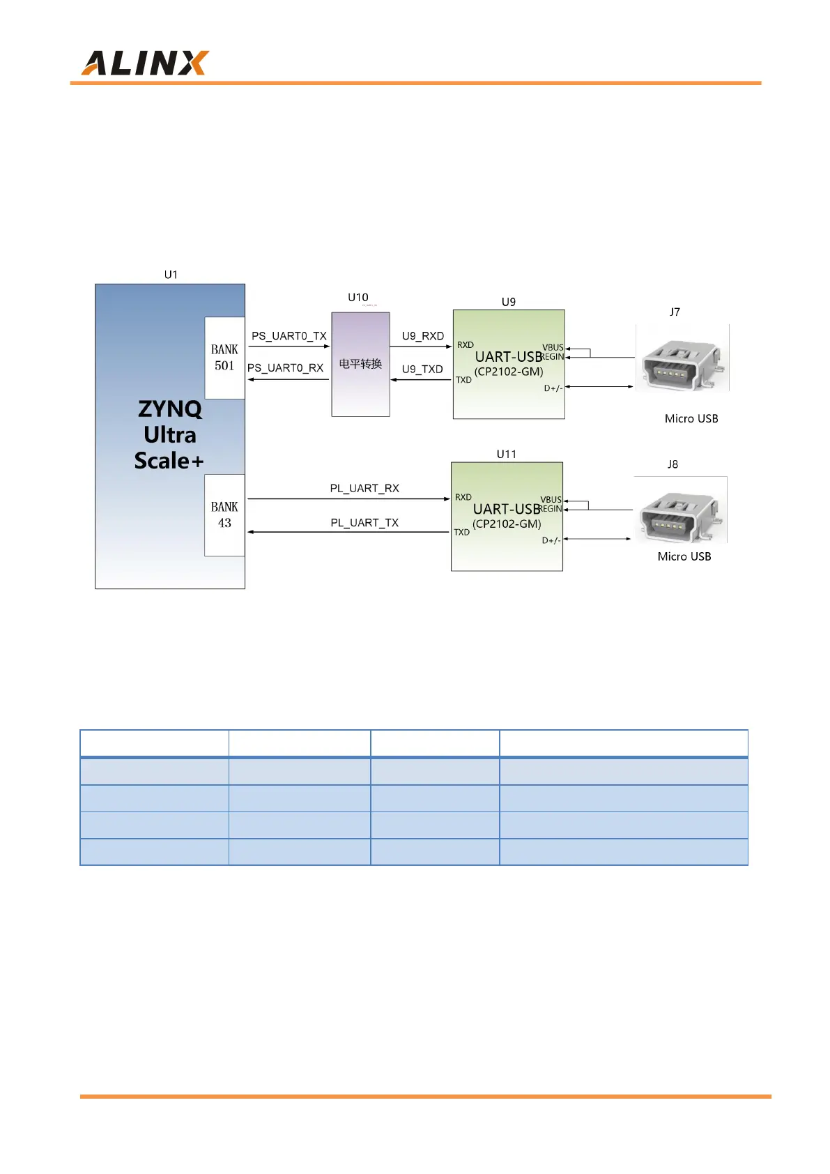
diagram of the USB Uart circuit design is shown in the figure below:
The schematic diagram of the USB Uart circuit design is shown in Figure
3-6-1:
Figure 3-6-1: USB to serial port schematic
USB to serial port ZYNQ pin assignment:
Part 3.7: SD Card Slot Interface
The AXU2CGB-E FPGA Development Board contains a Micro SD card
interface to provide user access to the SD card memory, the BOOT
program for the
ZU2CG
chip, the Linux operating system kernel, the file