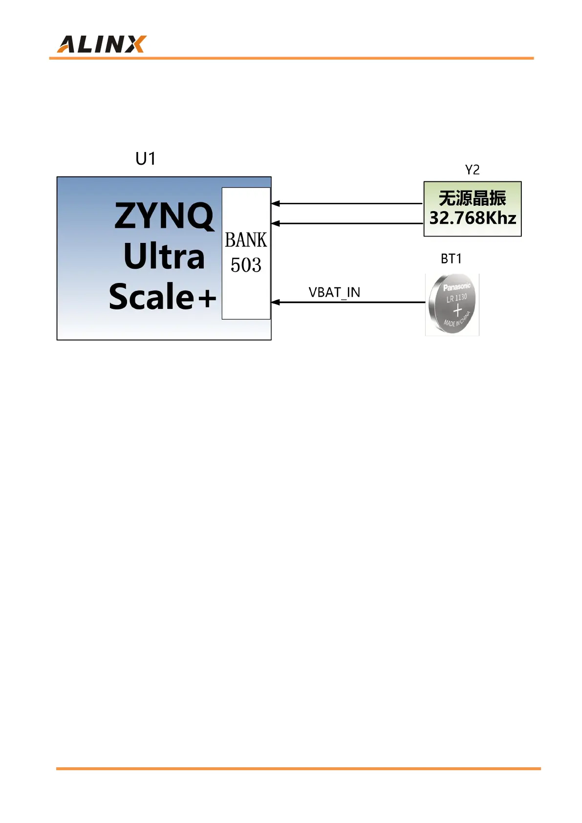
The BT1 on the development board is a battery Socket. After we put the coin
battery, even the system is off, the coin battery can also power the RTC system
and provide continuous time information.
Figure 3-13-1: RTC Schematic
Part 3.14: EEPROM and Temperature sensor
The AXU2CGB-E Fpga development board has an EEPROM onboard.
The model of the EEPROM is 24LC04, and the capacity is: 4Kbit (2 * 256 * 8bit),
which is connected to the PS terminal through the IIC bus.
A high-precision, low-power, digital temperature sensor chip is installed on
the AXU2CGB-E FPGA development board, and the model is LM75 from ON
Semiconductor. The temperature accuracy of the LM75 chip is 0.5 degrees.
The EEPROM and temperature sensor are mounted on the Bank500 MIO
of ZYNQ UltraScale+ through the I2C bus. Figure 3-14-1 is the schematic
diagram of EEPROM and temperature sensor