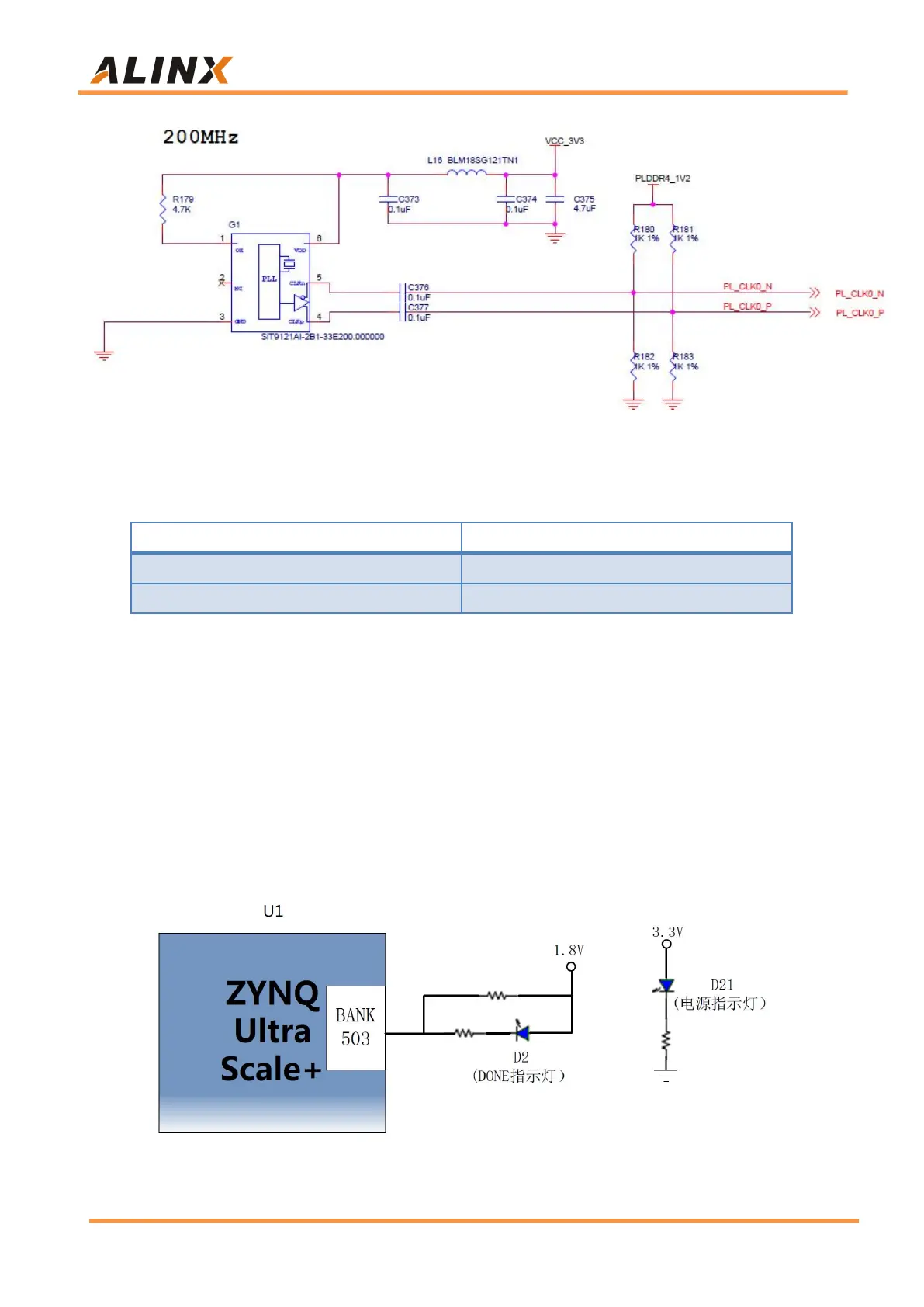
Figure 2-6-4: PL system clock source
Clock pin assignment:
Part 2.7: LED
There is a red power indicator (PWR) and a configuration LED (DONE) on
the ACU2CG core board. When the core board is powered on, the power
indicator will light up; after the FPGA configuration program, the configuration
LED light will light up. The LED Schematic in the Core Board is shown in Figure
2-7-1:
Figure 2-7-1: LED Schematic in the Core Board