EasyManua.ls Logo

Alinx AXU2CGB-E - Part 2.4: QSPI Flash

Alinx AXU2CGB-E
57 pages
Print Icon
To Next Page IconTo Next Page
To Previous Page IconTo Previous Page
Loading...
AXU2CGB-E User Manual
18
/
57
www.alinx.com
PS_DDR4_WE_B
PS_DDR_A14_504
AB24
PS_DDR4_CAS_B
PS_DDR_A15_504
AC24
PS_DDR4_RAS_B
PS_DDR_A16_504
AC23
PS_DDR4_ACT_B
PS_DDR_ACT_N_504
Y23
PS_DDR4_ALERT_B
PS_DDR_ALERT_N_504
U25
PS_DDR4_BA0
PS_DDR_BA0_504
V23
PS_DDR4_BA1
PS_DDR_BA1_504
W22
PS_DDR4_BG0
PS_DDR_BG0_504
W24
PS_DDR4_CS0_B
PS_DDR_CS_N0_504
W27
PS_DDR4_ODT0
PS_DDR_ODT0_504
U28
PS_DDR4_PARITY
PS_DDR_PARITY_504
V24
PS_DDR4_RESET_B
PS_DDR_RST_N_504
U23
PS_DDR4_CLK0_P
PS_DDR_CK0_P_504
W25
PS_DDR4_CLK0_N
PS_DDR_CK0_N_504
W26
PS_DDR4_CKE0
PS_DDR_CKE0_504
V28
Part 2.4: QSPI Flash
The FPGA core board ACU2CG is equipped with one 256MBit Quad-SPI
FLASH chip to form an 8-bit bandwidth data bus, the flash model is
MT25QU256ABA1EW9, which uses the 1.8V CMOS voltage standard. Due to
the non-volatile nature of QSPI FLASH, it can be used as a boot device for the
system to store the boot image of the system. These images mainly include
FPGA bit files, ARM application code, and other user data files. The specific
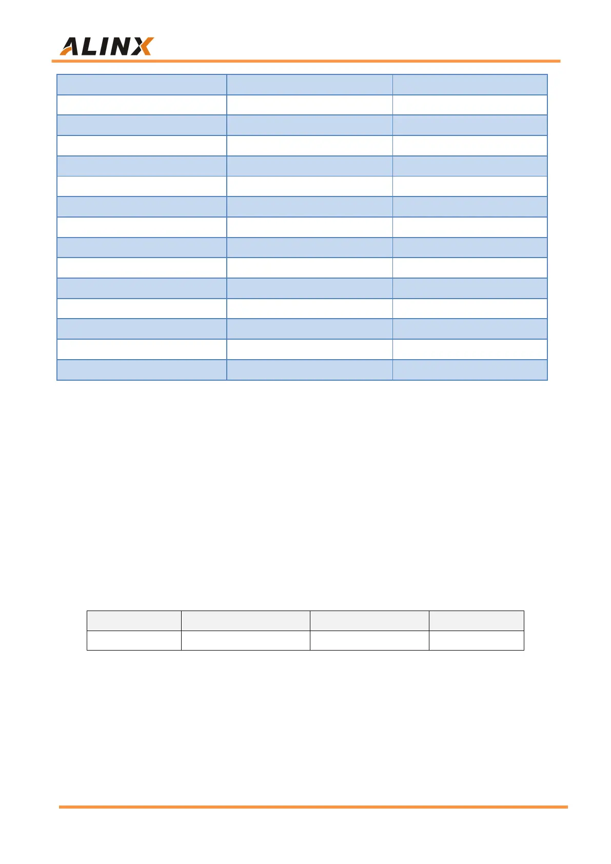
models and related parameters of QSPI FLASH are shown in Table 2-4-1.
Position
Model
Capacity
Factory
U5
MT25QU256ABA1EW9
256Mbit
Winbond
Table 2-4-1: QSPI FLASH Specification
QSPI FLASH is connected to the GPIO port of the BANK500 in the PS
section of the ZYNQ chip. In the system design, the GPIO port functions of
these PS ports need to be configured as the QSPI FLASH interface. Figure

Related product manuals