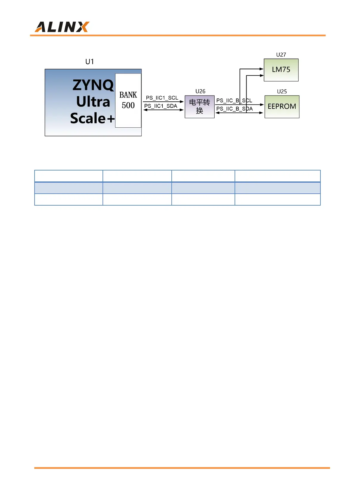
Figure 3-14-1: EEPROM and Sensor connection diagram
EEPROM pin assignment:
Part 3.15: User LEDs
There are 3 LEDs on the AXU2CGB-E Carrier board. including 1 power
indicator light, 1 User LED Controlled by PS side, and 1 User LED Controlled
by PL side. The user can control the user LED on and off through the program.
When the IO voltage of the connected user LED light is low, the user LED light
is off, and when the connected IO voltage is high, the user LED will be lit. The
schematic diagram of the user's LED light hardware connection is shown in
Figure 3-15-1: