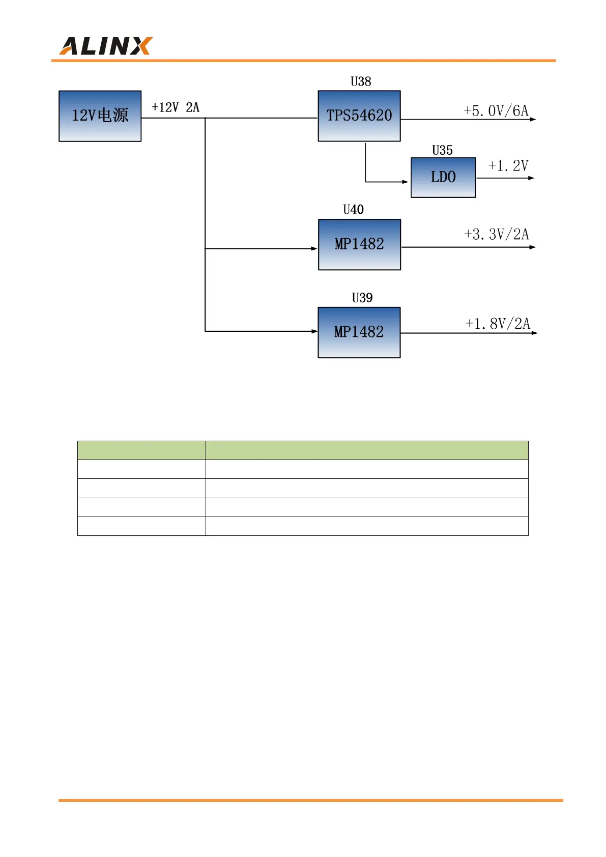
Figure 3-18-1: Carrier Board Power Schematic
The functions of each power distribution are shown in the following table:
Ethernet, USB2.0, BANK66 of Core Board
Ethernet, USB2.0, SD, DP, CAN, RS485
Part 3.19: ALINX Customized Fan
Because AXU2CGB-E generates a lot of heat when it works normally, we
add a heat sink and fan to the chip on the board to prevent the chip from
overheating. The control of the fan is controlled by the ZYNQ chip. The control
pin is connected to the IO of the BANK43 (AA11). If the IO level output is high,
the MOSFET is turned on and the fan is working. If the IO level output is low,
the fan stops. The fan design on the board is shown in Figure 3-19-1.