1–7Control Logic Wiring and Adapters
Publication 1336 IMPACT-6.2 – March 1998
Select 3
1
Pot UpPot Up
In modes 9, 10, and 15, the MOP value is not reset to 0 when you stop. In modes 28, 29, and
30, the MOP value is reset when you stop.
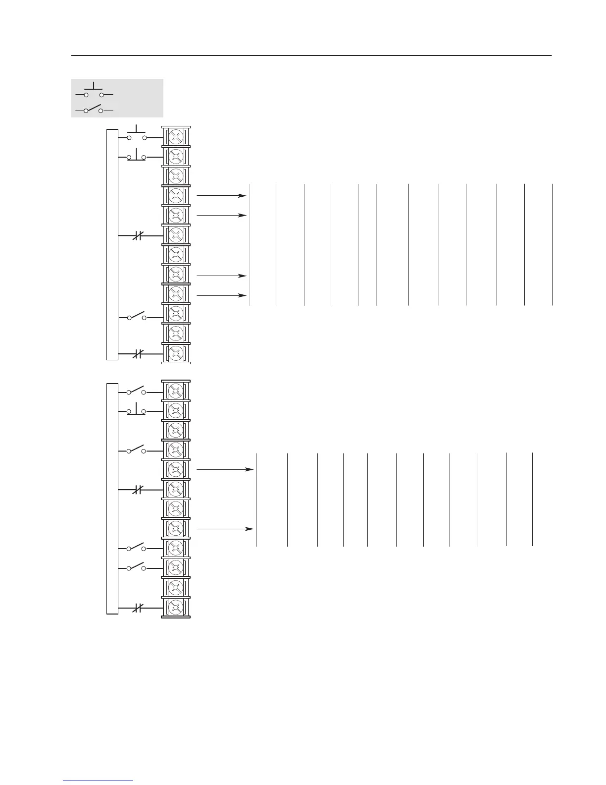
Momentary
Maintained
Common
Common
Common
Local Stop
Accel
Digital
Pot Up
Local
Speed Speed
Decel
Digital
Pot Dn
Stop
Type
12 13 14 15 16
Mode
19
20
21
22
23
24
25
26
27
28
29
30
Common
Common
Common
Digital
Pot Dn
2nd
Accel
Jog
Speed Speed Digital 1st
Decel
Digital
Pot Up
1st
Accel
7891011
Mode
Speed Speed Speed Digital
Pot Dn
2nd
Decel
19
20
21
22
23
24
25
26
27
28
29
30
User Connections User Connections
See Table 1.B. 1
Drive must be stopped to take Local Control.
Control by all other adapters is disabled (except Stop).
2
AB0291B
These inputs must be present before drive will start. 3
Speed Select 1
1
Enable
3
Not Stop
7
, Clear Fault
3,6
Speed Select 2
1
Speed Select 1
1
Enable
3
Select 2
1
Select 2
1
Select 2
1
Select 3
1
Control
2
Control
2
Select 3
1
Select 3
1
Not Stop
7
, Clear Fault
3,6
Reverse
5
Forward
5
Reverse
5
Forward
5
Reverse
5
Forward
5
Torque 3
10
Speed/
Torque 2
10
Speed/
Torque 1
10
Speed/
Process
Trim
Reverse
5
Forward
5
Torque 3
10
Speed/
Torque 2
10
Speed/
Torque 1
10
Speed/
Enable
Flux
Ramp
Reset
Torque 3
10
Speed/
Torque 2
10
Speed/
Torque 1
10
Speed/
Speed
Select 2
1
Process
Trim
Reset
Flux
Enable
Process
Trim
Reset Ramp
Run Reverse
5,11
Run Forward
5,11
Type
7
2nd/1st
2nd/1st
Not Ext Fault
4,8
Not Ext Fault
4,8
23 24 25
19
20
21 22
4 For Common Bus, this becomes Precharge Enable.
5 Bit 11 of Logic Options (parameter 17) must be 0 for reverse direction control.
6
For soft faults only. You need to recycle power to the drive to clear. For hard
faults, refer to the troubleshooting chapter.
7
To configure the stop type, refer to Logic Options (parameter 17).
8
This L Option must be present before the fault can be cleared and the drive
will start. This can be disabled through Fault Select 2 (parameter 22) and
Warning Select 2 (parameter 23).
9
Latched starts require a stop to stop the drive.
10
See Speed/Torque Select table.
Unlatched start.
11
Multi-Source, Three-Wire Control
L Option Mode (parameter 116) = 7 – 11, 19 – 22, 28, and 29
Start
9
Single-Source, Two-Wire Control
L Option Mode (parameter 116) = 12 – 16, 23 – 26, and 30
Jog
Speed
26
Select 3
1
13
12
Available in versions 2.02 and later.
Digital
Pot Dn
Speed
Digital
Pot Up
Speed
Select 2
1
Select 3
1
28 29
Digital
Digital
Pot Dn
Reverse
5
Forward
5
12,1312,13
30
Digital
Pot Up
Digital
Pot Dn
12,1312
12 12
 Loading...


