54 Rockwell Automation Publication MOTION-UM002E-EN-P - June 2016
Chapter 4 Configure an Articulated Independent Robot
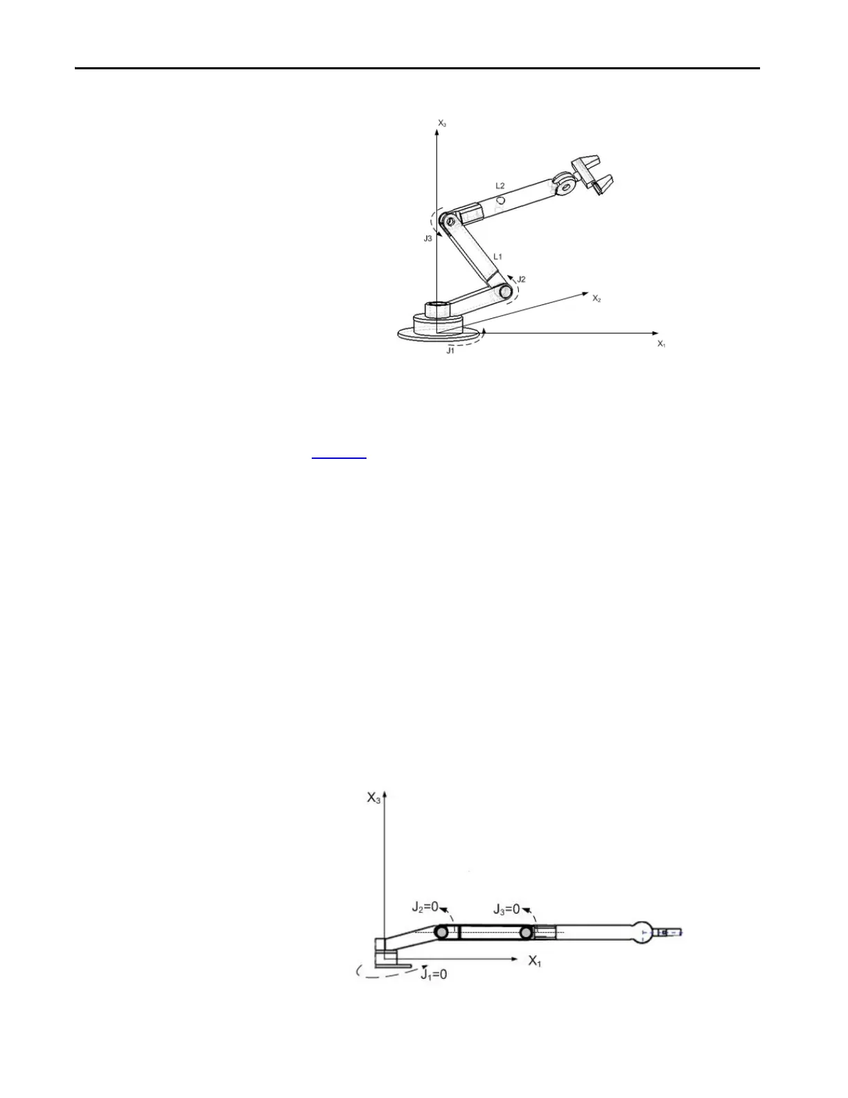
Figure 9 - Articulated Independent 1
Before you begin establishing the Joint-to-Cartesian reference frame
relationship, it is important to know some information about the Kinematic
mathematical equations used in the controllers. The equations were written as
if the Articulated Independent robot joints were positioned as shown in
Figure 10
.
• +J1 is measured counterclockwise around the +X3 axis starting at an
angle of J1=0 when L1 and L2 are both in the X1-X2 plane.
• +J2 is measured counterclockwise starting with J2=0 when L1 is parallel
to X1-X2 plane.
• +J3 is measured counterclockwise with J3=0 when L2 is aligned with
link L1.
When your robot is physically in this position, the Logix Designer application
Actual Position tags for the axes must be:
•J1 = 0
•J2 = 0
•J3 = 0
Figure 10 - Articulated Independent 2

 Loading...


